6
INSTALLATION, Cont.
MODELS 205 AND 210
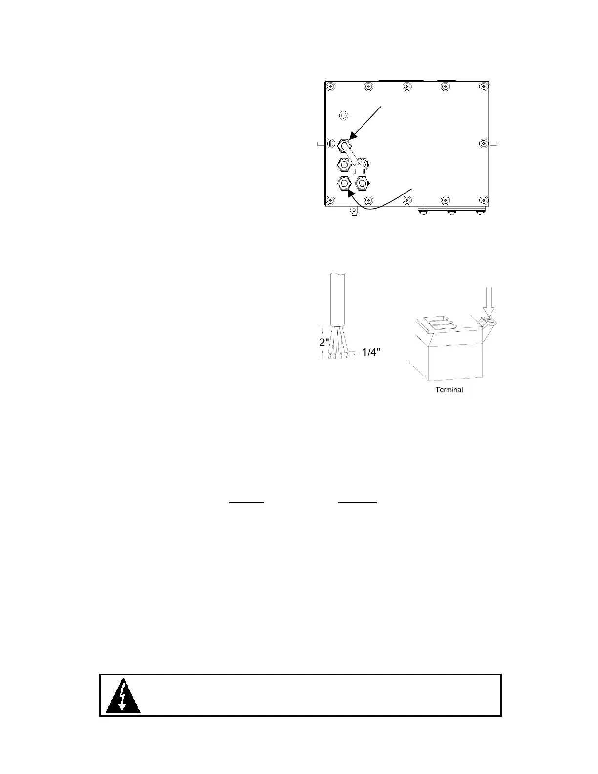
Remove the 12 screws securing the back panel to
the main housing, then loosen the bottom-left
cable gland connector for the load cell. This
gland connector is located on the rear panel of
the enclosure. Refer to Figure No. 4 for an
illustration of the connector layout.
1. Slip the single cable from the load cell or load
cell junction box through the gland connector
and into the enclosure.
2. Remove 2" of the outer insulation jacket then
remove 1/4" of insulation from each of the 4
wires and shield without sense leads or 6 wires
and shield with sense leads
Figure No. 4
(refer to Figure No. 5).
3. Connect each of the wires to terminal block P1
referring to the labels on the circuit board for
terminal connections. Refer to Figure No. 6 for
terminal block location.
4. To terminate a wire, first press down on the
release bar for the terminal, insert the wire into
the terminal opening then allow the release bar
to return to its original position, locking the wire
in place. Repeat the procedure until all of the
wires are in place.
5. Route the load cell cable through the two cable
clips provided on the upper and left sides of
the enclosure interior.
Figure No. 5
NOTE!
If the sense leads are NOT used, you must install plug-in jumpers at J4 and J5 adjacent
to the terminal block. These jumpers attach the sense leads to the excitation leads. If sense
leads ARE used (as in motor truck scales), these plug-in jumpers should be positioned on one
plug-in pin only or removed and stored for later use.
LOAD CELL CONNECTOR P1
PIN NO. Function
1 + EXCITATION
2 + SENSE
3 + SIGNAL
4 SHIELD
5 - SIGNAL
6 - SENSE
7 - EXCITATION
LOAD CELL CONNECTIONS WITH OVER 30 FEET OF CABLE
For installations with over 30 feet of cable between the indicator and the load cells, sense wires
should be used. The sense wires must be connected between the +SENS, -SENS terminals on the
indicator and the +EXCITATION, -EXCITATION wires of the load cells or the +SENS, -SENS
terminals of the load cell trim board or the section seal trim board. For the indicator to use the
sense wires, the +SENS jumper J4 and the -SENS jumper J5 must be open (see Figure No. 6).
CAUTION!
When in parallel runs, locate Load Cell cables a minimum of 24" away
from all AC wiring.
115 to 230 VAC
0.4 Amp max.
Load Cell

 Loading...