5
CAUTION!
Disconnect any external load cell power supply before connecting load
cells to the instrument. Failure to do so will result in permanent damage to the
instrument.
INSTALLATION
Before beginning installation of your Model 200 Series Weight Indicating Instrument, make certain
that the instrument has been received in good condition. Carefully remove the instrument from the
shipping carton and inspect it for any evidence of damage (such as exterior dents or scratches)
that may have taken place during shipment. Keep the carton and packing material for return
shipment if it should become necessary. It is the responsibility of the purchaser to file all claims for
any damages or loss incurred during transit.
Mounting the Model 200
The Model 200 Indicator is housed in a NEMA 12/IP52 panel mount enclosure that is normally
mounted to an equipment panel through a rectangular cutout. Refer to Figure No. 1 for the cutout
dimensions for the NEMA 12/IP52 enclosure. (
Figure No. 1 to be added at a later date
).
Regardless of where you mount your Model 200, it should be in a safe area where it will not be in
the way of normal traffic. The location chosen should be free of temperature extremes and water. It
should be in a location where the display is easily viewed and is not subject to direct sunlight. The
indicator should be mounted such that it is within easy reach of the operator.
Mounting the Models 205 and 210
NOTE!
Should your 205/210 indicator come already installed on a scale, the following information
describing the installation of the instrument does not apply.
The Models 205 and 210 Indicators are housed in a NEMA 4X/IP66 stainless steel wall or desk-
mount enclosure. The 205/210 gimbal may be mounted on a desktop or other smooth, flat,
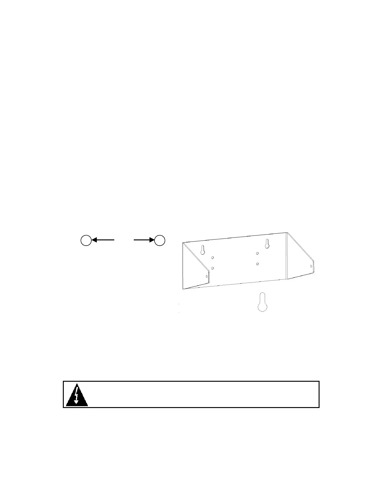
horizontal surface or may be mounted on a wall. Refer to Figure No. 2 for a layout of wall-
mounting bolts.
6.00"
Figure No. 2
If wall mounted, make certain that the mounting surface is strong enough to support the 8.2lb
instrument. The mounting location should be where the display is easily viewed while being close
enough to provide the operator easy access to the keypad. Carefully lay out the mounting hole
locations, then drill and install the anchor bolts. Attach the gimbal to the wall and securely tighten
the retaining bolts.
LOAD CELL CONNECTION
MODEL 200
The load cell cable is terminated via a connector on the rear panel. Refer to Figure No. 3 for an
illustration of the connector layout. Connect to the appropriate connector on the rear panel.
(
Figure No. 3 to be added at a later date
).
Clearance for
#10 size screw
✚
✚✚
✚
✚

 Loading...