pCO Sistema
Code: +030220336 - rel. 1.5 - 22/12/10
32
4.2 Power supply
Power supply to the pCO
3
, pCO
1
and pCO
C
(controller with terminal connected): 28 to 36 Vdc +10/-20% or 24 Vac +10/-15% 50 to 60 Hz;
Maximum current P= 15 W (Vdc power supply), P= 40 VA (Vac)
Power supply to the pCO
XS
: 20/60 Vdc or 24 Vac ± 15% 50 to 60 Hz.
Maximum current P=6.1 W (Vdc), P=8 VA (Vac)
power supplies other than those specified may seriously damage the system;
use a Class 2 safety transformer, rated to 50 VA in the installation to supply just one pCO3, pCO1 and pCOC controller; for pCOXS controller is used a same
transformer of 25VA.
separate the power supply to the pCO controller and the terminal (or multiple pCO controllers and terminals) from the power supply to the other electrical
devices (contactors and other electromechanical components) inside the electrical panel;
if the power transformer secondary is earthed, check that the earth wire is connected to terminal G0; this must be followed for all devices connected to the pCO;
if more than one pCO board is connected in pLAN network, make sure that G and G0 are always connected in the same way (G0 must be the reference for
make sure that G and G0 are always connected in the same way (G0 must be the reference for make sure that G and G0 are always connected in the same way (G0 must be the reference for
make sure that G and G0 are always connected in the same way (G0 must be the reference for
all the boards);
all the boards);all the boards);
all the boards);
a yellow LED indicates when the pCO is powered.
4.3 Connecting the analogue inputs
The analogue inputs on the pCO can be configured for the most commonly used sensors on the market: NTC, PT1000, 0 to 1 V, 0 to 5 V ratiometric, 0 to 10 V, 0 to 20 mA,
4 to 20 mA. The type of sensor can be selected by setting a parameter on the user terminal (if featured by the application program) and from hardware selection for
pCO
1
or pCO
c
4.3.1
4.3.14.3.1
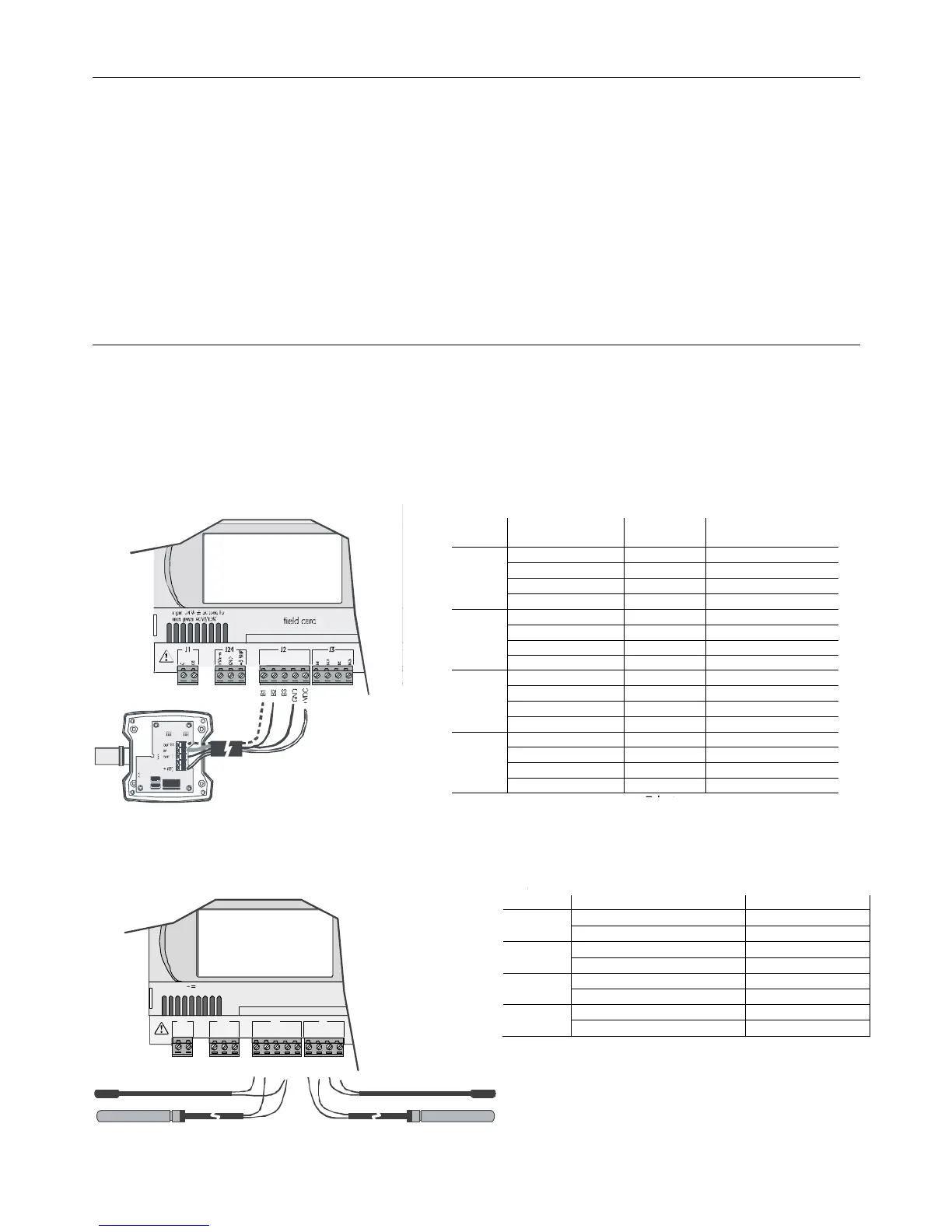
4.3.1 Connecting active temperature and humidity probes
Connecting active temperature and humidity probesConnecting active temperature and humidity probes
Connecting active temperature and humidity probes
The pCO can be connected to all CAREL AS*2 series active temperature and humidity probes configured with 0 to 1 V or 4 to 20 mA signals.
For the temperature probes, use the 4 to 20 mA or NTC configuration, as the 0/1 Vdc signal is limited to the restricted 0-1 V range and therefore is not always
compatible with the standard 10 mV/°C signal of the CAREL probes (for temperatures below 0°C and above 100°C, a probe alarm may be generated).
The inputs must be configured for 0 to 1 V or 4 to 20 mA signals by the application program resident in flash memory.
The connection diagram is shown below:
Fig. 4.a
Fig. 4.aFig. 4.a
Fig. 4.a
4.3.2
4.3.24.3.2
4.3.2 Connecting universal NTC temperature probes
Connecting universal NTC temperature probesConnecting universal NTC temperature probes
Connecting universal NTC temperature probes
All the analogue inputs are compatible with 2-wire NTC sensors. The inputs must be configured for NTC signals by the application program resident in flash memory.
The connection diagram is shown below:
G
G0
+V
te rm
GN D
+5 V
REF
VG
VG0
Y1
Y2
Y3
Y4
ID1
ID2
ID3
ID4
ID5
ID6
ID7
ID8
J1 J24 J2 J3
J4 J5
J21
J10J9
ID 15H
field card serial card
input: 24 V / ;50 to60 Hz
max. power:40VA/15W
B1
B2
B3
GND
+VDC
B4
BC4
B5
BC5
Fig. 4.b
Fig. 4.bFig. 4.b
Fig. 4.b
Warning:
Warning: Warning:
Warning: the two NTC probe wires are equivalent, as there is no polarity, therefore no special order needs to be followed when connecting to the terminal block.
 Loading...


