pCO Sistema
Code: +030220336 - rel. 1.5 - 22/12/10
47
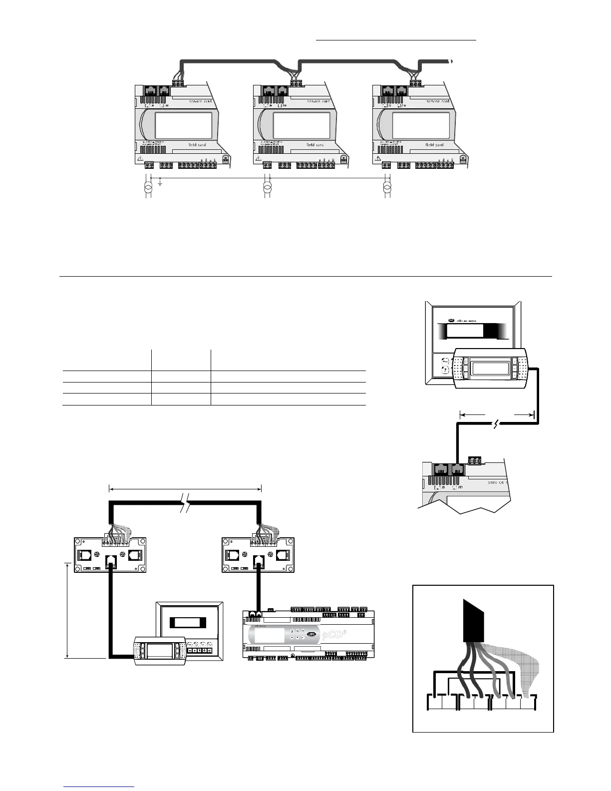
Fig. Fig. 5.r shows a diagram of a number of boards connected in a pLAN network and powered by different transformers with the same earth
; this is a typical
application for a number of boards inside different electrical panels.
G
G0
RX-/TX+
RX+/TX-
GND
G
G0
RX-/TX+
RX+/TX-
GND
G
G0
RX-/TX+
RX+/TX-
GND
AWG 20/22 AWG 20/22 AWG 20/22
Fig. 5.r
Fig. 5.rFig. 5.r
Fig. 5.r
IMPORTANT WARNINGS:
IMPORTANT WARNINGS:IMPORTANT WARNINGS:
IMPORTANT WARNINGS:
• the earth connection must be made to the same point in the earth line (same earth pole, for all the pCO boards)
• with these configurations (Figs. 5.e, 5.f and 5.g) Class 2 safety transformers must be installed.
• if the G0 terminals of the pCO controllers are connected toget
if the G0 terminals of the pCO controllers are connected togetif the G0 terminals of the pCO controllers are connected toget
if the G0 terminals of the pCO controllers are connected together, connect the pLAN cable shield to one pCO only
her, connect the pLAN cable shield to one pCO onlyher, connect the pLAN cable shield to one pCO only
her, connect the pLAN cable shield to one pCO only
.
5.7 Remote installation of a terminal in a pLAN network
When the pCO boards are connected in a pLAN network, the terminal can be remotely-installed at a distance of up to 50 metres, if using a telephone cable, while it
can be located at a distance of up to 500 metres if using a shielded cable, TCONN6J000 and a separate power
supply.
Note
NoteNote
Note: to reach the maximum length, use a bus layout with branches that do not exceed 5 m.
The following figures show the connection diagrams for the various configurations.
If using the terminal in a residential environment, the cable must be always shielded
If using the terminal in a residential environment, the cable must be always shieldedIf using the terminal in a residential environment, the cable must be always shielded
If using the terminal in a residential environment, the cable must be always shielded.
The maximum distance between the pCO and the user terminal is shown in the following table:
type of cable
type of cabletype of cable
type of cable
power supply
power supply power supply
power supply
di
didi
distance
stancestance
stance
power supply
power supplypower supply
power supply
telephone 50 m taken from pCO (150 mA)
AWG24 shielded cable 200 m taken from pCO (150 mA)
AWG20/22 shielded cable 500 m separate power supply via TCONN6J000
Tab. 5.a
Tab. 5.aTab. 5.a
Tab. 5.a
The maximum distance between two pCO
3
controllers with AWG20/22 shielded cable is 500 m.
Important:
Important: Important:
Important: do not reverse the GND and +Vdc cables.
 Loading...


