pCO Sistema
Code: +030220336 - rel. 1.5 - 22/12/10
38
4.5 Connecting the analogue outputs
4.5.1
4.5.14.5.1
4.5.1 Connecting the 0 to 10 V
Connecting the 0 to 10 V Connecting the 0 to 10 V
Connecting the 0 to 10 V analogue outputs
analogue outputsanalogue outputs
analogue outputs
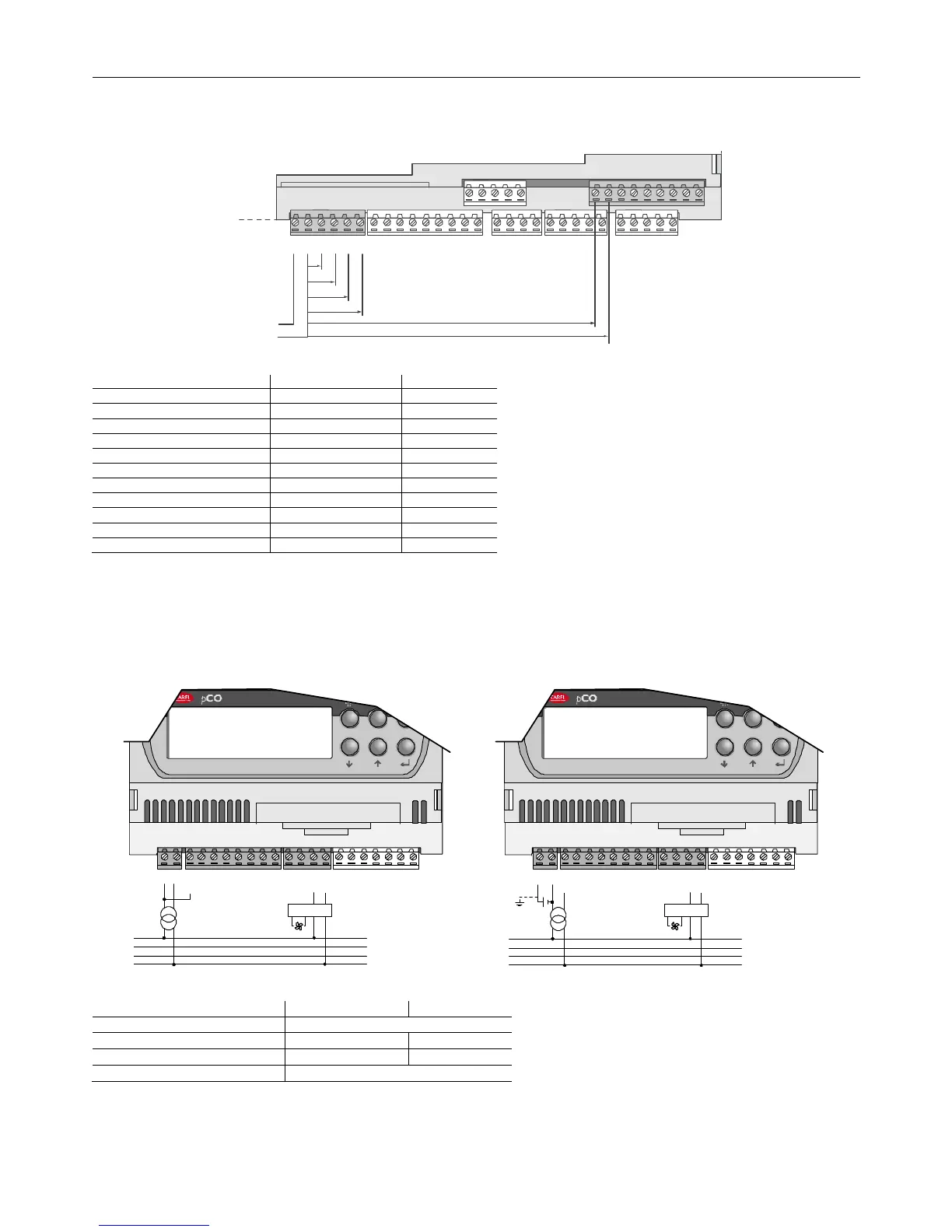
The pCO provides 0-10V optically-isolated analogue outputs, powered externally at 24Vac/Vdc.
Fig. 4.n shows the electrical connection diagram; the 0 V (zero) of the power supply is also the reference for the output voltage.
The table below shown summarises the distribution of the analogue outputs according to the versions available.
VG
VG0
Y1
Y2
Y3
Y4
Y5
Y6
B9
BC9
B10
BC10
ID17
ID18
IDC17
Serial Card
24Vac/Vdc
V
out
V
out
V
out
V
out
V
out
V
out
0V
Fig. 4.n
Fig. 4.nFig. 4.n
Fig. 4.n
no. of analogue outputs
no. of analogue outputsno. of analogue outputs
no. of analogue outputs
reference
referencereference
reference
terminals
terminalsterminals
terminals
terminals
terminalsterminals
terminals
terminals
terminalsterminals
terminals
terminals
terminalsterminals
terminals
Tab. 4.l
Tab. 4.lTab. 4.l
Tab. 4.l
Warning: on the pCO
Warning: on the pCOWarning: on the pCO
Warning: on the pCO
XS
XSXS
XS
the outputs are not optically-isolated. Also remember that the internal circuit of the power supply to the pCO
XS
is isolated.
4.5.2
4.5.24.5.2
4.5.2 Connecting the PWM analogue outputs
Connecting the PWM analogue outputsConnecting the PWM analogue outputs
Connecting the PWM analogue outputs
The pCO
1
and the pCO
XS
provide a PWM analogue output for phase cutting speed controllers. Fig.4.o shows the most common electrical connection diagrams.
Y1
Y2
Y3
GND
SYNC
B1
B2
B3
B4
GND
+5VREF
+24VDC
G
G0
J3
SERIAL CARD
built-in terminal
xs
L1
N
Y1
Y2
Y3
GND
SYNC
B1
B2
B3
B4
GND
+5VREF
+24VDC
G
G0
J3
SERIAL CARD
built-in terminal
xs
MCHRTF
L1
N
MCHRTF
+
Fig. 4.o
Fig. 4.oFig. 4.o
Fig. 4.o
no. of analogu
no. of analoguno. of analogu
no. of analogue outputs
e outputse outputs
e outputs
reference
referencereference
reference
pCO
pCOpCO
pCO
terminals
terminalsterminals
terminals not available
pCO
pCOpCO
pCO
terminals
terminalsterminals
terminals Y3 G0
pCO
pCOpCO
pCO
terminals
terminalsterminals
terminals Y3, Y4 VG0
pCO
pCOpCO
pCO
terminals
terminalsterminals
terminals not available
Tab. 4.m
Tab. 4.mTab. 4.m
Tab. 4.m
Note:
Note: Note:
Note: the power supply to the circuit measuring the zero crossing is at terminal G on the pCO
1
and terminal SYNC on the pCO
XS
, and must be 24 Vac, in phase with
the power supply to the actuator: for three-phase power supply, use the same phase to power the pCO
XS
and the actuator.
 Loading...


