pCO Sistema
Code: +030220336 - rel. 1.5 - 22/12/10
41
5. CONFIGURATION OF THE PLAN NETWORK
5.1 Introduction
All the pCO controllers can be connected together and to other Carel devices in a local network (pLAN), without requiring optional devices, thus allowing the
communication of data and information from one location (node) to another.
The pCO terminals can display the variables (temperature, humidity, pressure, I/O, alarms) from one controller only at any one time. The terminal does not need to be
connected to the pCO for the normal operation of the controller, however it can be used for the initial programming of the fundamental parameters.
If one or more terminals are disconnected or malfunctioning, the control program continues to operate correctly on each pCO board.
In general, the application program can monitor the status of the network and the terminals and respond in the event of malfunctions.
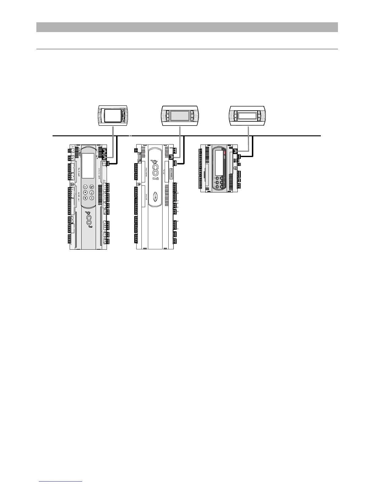
The figure below shows a possible pLAN network connection diagram.
pCO
Fig. 5.a
Fig. 5.aFig. 5.a
Fig. 5.a
The standard communication speed over the network is 62500 bps but some devices also support speeds of 115200 bps.
All the units in the network must in any case use the same speed.
A maximum of 32 units can be connected, including:
- pCO controllers, running the control program;
- boards that extend the I/O functions (such as the EVD200 driver);
- terminals (LED, 4x20 LCD and graphic).
Each unit in the pLAN is identified by a unique address, that is, a number between 1 and 32. Address 32 can only be assigned to a terminal.
The programs for the different applications (e.g.: standard chiller, standard air-conditioners, compressor racks, ...) cannot be automatically integrated into a local
network: they must be configured considering the architecture of the system and using the developing CAREL tool.
Each pCO board connected to the network can manage up to 3 pLAN terminals at the same time. The values are displayed simultaneously and not independently on
each terminal, as if they were connected in parallel: for this reason, the pCO cannot control different types of terminals at the same time (for example, one pGD
1
and
one pGD
3
).
A terminal associated with a certain board is defined as:
- private (“Pr
PrPr
Pr”) if it exclusively displays the output of that board;
- shared (“Sh
ShSh
Sh”) if either automatically or from the keypad it can be switched between more than one board;
- shared with printer (“Sp
SpSp
Sp”) if, as well as being shared, it is fitted with a RS232 serial board for connecting a printer (only for the old PCOT and PCOI terminals, not the
pGD).
Each pCO maintains constantly updates the display on the private terminals, while the shared terminals are only updated only if the pCO controller in question has
control over the terminal at that moment.
 Loading...


