pCO Sistema
Code: +030220336 - rel. 1.5 - 22/12/10
39
4.5.3
4.5.34.5.3
4.5.3 Optional modules
Optional modulesOptional modules
Optional modules
Module for
Module forModule for
Module for converting a PWM output to a 0 to 10 V analogue output or 4
converting a PWM output to a 0 to 10 V analogue output or 4 converting a PWM output to a 0 to 10 V analogue output or 4
converting a PWM output to a 0 to 10 V analogue output or 4 to 20 mA.
to 20 mA.to 20 mA.
to 20 mA.
A special module is used to convert a PWM output (5 V pulses) into a linear 0 to 10 V or 4 to 20 mA analogue output (code CONV0/10A0).
The control signal (at the input terminals it is optically-isolated from the rest of the module) must have a maximum amplitude of 5 V and a period of between 8ms and
200 ms. The 0 to 10 V output can be connected to a maximum load of 2kΩ, with a maximum ripple of 100 mV, while the 4 to 20 mA current output can be connected
to a maximum load of 280Ω, with a maximum overshoot of 0.3 mA.
The module measures 87x36x60 mm (2 DIN modules) and has IP20 index of protection.
Module for converting a 0 to 10 V analogue output to an SPDT digital output (code CONVONOFF0)
Module for converting a 0 to 10 V analogue output to an SPDT digital output (code CONVONOFF0)Module for converting a 0 to 10 V analogue output to an SPDT digital output (code CONVONOFF0)
Module for converting a 0 to 10 V analogue output to an SPDT digital output (code CONVONOFF0)
This module is used to convert a 0 to 10 V analogue output (Yn) to an ON/OFF relay output. The control signal Yn (at the input terminals it is optically-isolated from
the rest of the module), to ensure the relay switches from OFF to ON, must have a minimum amplitude of 3.3 V. The relay is SPDT with a maximum current of 10 A
and a maximum inductive load of 1/3 HP. The module measures 87x36x60 mm (2 DIN modules) and has IP20 index of protection.
Module for dividing the number of pulses at the digital input by 8 (code PCO208DI00)
Module for dividing the number of pulses at the digital input by 8 (code PCO208DI00)Module for dividing the number of pulses at the digital input by 8 (code PCO208DI00)
Module for dividing the number of pulses at the digital input by 8 (code PCO208DI00)
This module is used to independently divide the frequency of two signals by a factor of 8. The two input signals (at the input terminals they are optically-isolated from
the rest of the module) must have a amplitude of between 10 and 20V, a duration greater than 10 ms and a maximum frequency of 10 Hz.
The module measures 87x36x60 mm (2 DIN modules) and has IP20 index of protection.
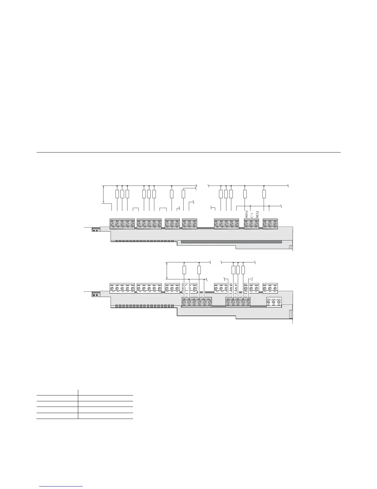
4.6 Connecting the digital outputs
The pCO features digital outputs with electromechanical relays and for ease of installation, the common terminals of some of the relays have been grouped together. If
a diagram in Fig. 4.p is used, the current at the common terminals must not exceed the rating (nominal current) of an individual terminal (8 A).
4.6.1
4.6.14.6.1
4.6.1 Electromechanical relay digital outputs
Electromechanical relay digital outputsElectromechanical relay digital outputs
Electromechanical relay digital outputs
C1
NO1
NO2
NO3
C1
C4
NO4
NO5
NO6
C4
C7
NO7
C7
NO8
C8
NC8
NO13
C13
NC13
C9
NO9
NO10
NO11
C9
N
L
110/230-24Vac
NO14
C14
NC14
NO15
C15
NC15
C16
NO16
NO17
NO18
C16
N
L
110/230-24Vac
Fig. 4.p
Fig. 4.pFig. 4.p
Fig. 4.p
The relays are divided into groups, according to the insulation distance. Inside each group, the relays have just basic insulation and thus must have the same voltage
(generally 24Vac or 110-230Vac).
Between the groups, instead, there is double insulation and thus the groups can have different voltages. In any case there is double insulation from the rest of the
controller.
4.6.2
4.6.24.6.2
4.6.2 Changeover outputs
Changeover outputsChangeover outputs
Changeover outputs
Some relays feature changeover outputs:
 Loading...


