pCO Sistema
Code: +030220336 - rel. 1.5 - 22/12/10
46
5.5 Setting the pLAN address on the pCO
1
, pCO
XS
, pCO
C
and pCO
3
The pCO
1
, pCO
XS
, pCO
C
and pCO
3
controllers do not have dipswitches for setting the pLAN network address: the pLAN address can set from any terminal, pGD0, pGD1,
pGD2, pGD3 or built-in on the models where fitted. To set the address from an external terminal (not built-in), proceed as follows.
1) Set address 0 on the terminal (see the previous sections for details on how to set this address).
2) Power down the pCO.
3) Remove any pLAN connections from the pCO to other controllers.
4) Connect the terminal to the pCO.
5) Power up the pCO, pressing the UP and ALARM buttons together on the terminal. After a few seconds, the pCO commences the start-up sequence, and the
display shows a screen similar to the one below:
####################
selftest
please wait...
####################
Fig. 5.n
Fig. 5.nFig. 5.n
Fig. 5.n
6) When this screen appears, wait 10 seconds and then release the buttons.
7) The pCO stops the start-up sequence and shows a configuration screen similar to the one below:
pLan address: 0
UP: increase
DOWN: decrease
ENTER: save & exit
Fig. 5.o
Fig. 5.oFig. 5.o
Fig. 5.o
1) Then set the pLAN address using the UP and DOWN buttons on the terminal.
8) Confirm the address by pressing the ENTER button: the pCO completes the start-up sequence and uses the specified address.
Note:
Note:Note:
Note: step 6) is only required for the pGD2 or pGD3 terminals. To modify the address from a Built-In terminal, steps 1) and 3) are not needed; the rest of the
procedure is the same as described above.
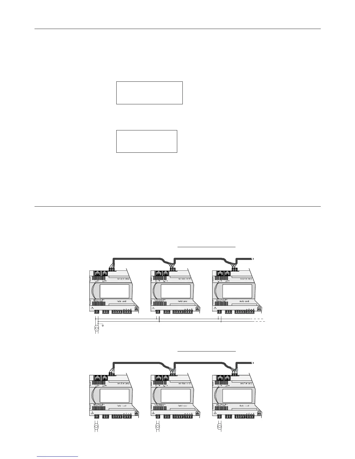
5.6 pLAN electrical connections between the pCO controllers
The connection of the pCO controllers in the pLAN is carried out using an AWG20/22 shielded cable, twisted pair plus shield, with a capacitance between the wires of less
than 90 PF/m.
Maximum pLAN network length:
Maximum pLAN network length: Maximum pLAN network length:
Maximum pLAN network length: 500 m with AWG22 cable, twisted pair with shield.
The boards are connected in parallel with reference to plug-in connector J11.
IMPORTANT:
IMPORTANT:IMPORTANT:
IMPORTANT: observe the network polarity: RX/TX+ on one board must be connected to RX/TX+ on the other boards; the same is true for RX/TX-.
Fig. 5.p shows a diagram of a number of boards connected in a pLAN network and powered by the same transformer, typical for a number of boards connected inside
the same electrical panel.
AWG 20/22 AWG 20/22 AWG 20/22
G
G0
RX-/TX+
RX+/TX-
GND
G
G0
RX-/TX+
RX+/TX-
GND
G
G0
RX-/TX+
RX+/TX-
GND
Fig. 5.p
Fig. 5.pFig. 5.p
Fig. 5.p
Fig. 5.q shows a diagram of a number of boards connected in a pLAN network and powered by different transformers (with G0 not earthed), typical of a number of
boards inside different electrical panels.
G
G0
RX-/TX+
RX+/TX-
GND
G
G0
RX-/TX+
RX+/TX-
GND
G
G0
RX-/TX+
RX+/TX-
GND
AWG 20/22 AWG 20/22 AWG 20/22
Fig. 5.q
Fig. 5.qFig. 5.q
Fig. 5.q
 Loading...


