pCO Sistema
Code: +030220336 - rel. 1.5 - 22/12/10
44
5.3 Installing the pGD2 and pGD3 terminals
The connection between the terminal and the pCO is made only using an AWG20/22 shielded cable, terminated with 3-pin plug-in connectors.
To make the connection, simply plug one of the connectors into the “RS485” jack on the terminal and the other to connector
• J6 on the pCO
XS
,
• J11 on the pCO
1
, pCO
C
, pCO
3
.
The pGD
2
and pGD
3
terminals can set the network address and communication speed from a menu. To access this menu, press any point on the touch screen together
with the UP and PRG buttons; alternatively, access is also possible by pressing UP, DOWN, ENTER at the same time. In both cases, after 1 second a screen similar to the
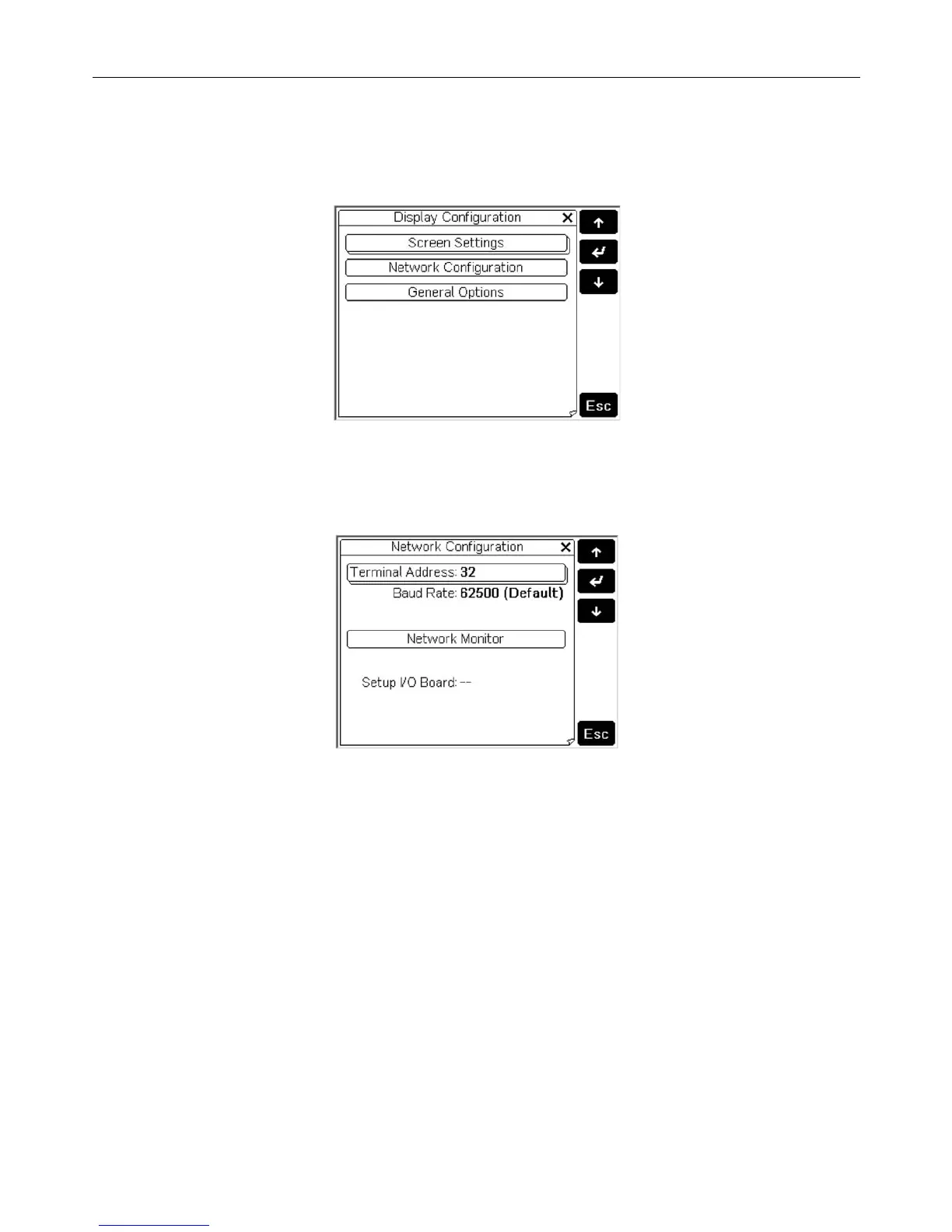
one below will be displayed:
Fig. 5.l
Fig. 5.lFig. 5.l
Fig. 5.l
To access a menu item, simply press the touch screen on the item or, alternatively, press the UP or DOWN button until selecting the item, then confirm with ENTER.
To change the value of a field after having selected it (a field is selected when the cursor is flashing on the field), press the UP or DOWN button until reaching the
desired value, then press ENTER to save the value. Pressing ESC before ENTER cancels the changes made to the field. The buttons available during the configuration
phase are visible on the right-hand side of the display. The network configuration options are available under “Network Configuration”. When selecting this item, the
terminal will display a screen similar to the one below:
Fig. 5.m
Fig. 5.mFig. 5.m
Fig. 5.m
The following options are available.
The following options are available.The following options are available.
The following options are available.
• Terminal Address
Terminal AddressTerminal Address
Terminal Address: used to set the address of the terminal, from 1 to 32.
If the value “--” is set (two dashes are displayed) the terminal will communicate with the pCO board using the Local terminal protocol (point-to-point) rather
than pLAN: the “Baud Rate”, “Network Monitor” and “Setup I/O Board” fields will no longer be displayed, as they have no meaning.
• Baud Rate
Baud RateBaud Rate
Baud Rate: used to set the pLAN communication baud rate. The options are 62500 bps (default) and 115200 bps. The 115200 bps option must only be set if all
the devices in the network are configured for this speed; note that not all pLAN support devices the 115200 bps setting.
• Network Monitor
Network MonitorNetwork Monitor
Network Monitor: used to display the network status. For further information, see the user manual for the pGD2/3 terminals.
• Setup I/O Board
Setup I/O BoardSetup I/O Board
Setup I/O Board: used to modify the list of terminals associated with each individual pCO board. To do this, select the address of the desired board (only the
boards that are effectively on line can be selected) and confirm by pressing ENTER: then press the “Setup” button on the display to start the configuration
procedure already described for the pCOI/pCOT terminals.
Important:
Important:Important:
Important: like all the pGD* terminals, the pGD
2
and pGD
3
cannot be configured as “Sp” (shared with printer) as they have no printer output. Selecting this mode has
no effect on the management of the printed messages. During operation, the terminal monitors special conditions of the pLAN network, and highlights these with
messages on the display, as illustrated below.
• Message “Starting up, please wait to ”: the terminal has just been started and/or is initiating communication.
• Message “Please wait...”: the procedure for assigning the private or shared terminals to a pCO has just ended and the terminal is awaiting the start of
communication.
• Message “No network link: terminal alone”: the pLAN protocol has been selected and no pCO is detected within 40 s from power-up, or alternatively the
network is inactive (no package received) for at least 20 s during normal operation.
• Message “I/O board (at address xx) fault”: the pLAN protocol has been selected and the terminal has lost communication with the pCO whose output it was
displaying for more than least 8 s.
• Message “No I/O board configured for this terminal”: the pLAN protocol has been selected and the terminal is not among those configured for the pCO in the
network. The message is displayed 40 s after power-up or around 8 seconds after ending the procedure for assigning the terminals to a pCO.
 Loading...


