42
Two methods are used to add and remove stages of cooling
for units with more than one compressor. The first method
causes the unit to operate around its steady-state number of
stages. For example, if the correct number of stages is between
0 and 1, this method will cause the first stage to cycle. If the
correct number of stages is between 1 and 2, this method will
cause the second stage to cycle. The second method causes the
unit to find the steady-state number of stages. Details of these
methods are provided below.
The control uses two methods to add a stage of compressor
cooling. The first method will add a stage of cooling when the
Cooling Demand (Operating Modes
→
COOL
→
SPT
→
DMD.C) plus the change in cool demand (Operating
Modes
→
COOL
→
SPT
→
TRD.C) times the Cool Thermal Lag
Factor (Operating Modes
→
COOL
→
SPT
→
C.LAG) is greater
than the SPT Cool Demand (+) Level (Operating Modes
→
COOL
→
SPT
→
CL.PD).
DMD.C + TRD.C * C.LAG > CL.PD
This method is only used after the Compressor Settling
Time (Configuration
→
UNIT
→
SAT.T), has been exceeded
and the supply-air temperature is slowly increasing. The sec-
ond method will add a stage of cooling when Cool Demand is
greater than the SPT Cool Demand (+) Level plus 0.5° F
(DMD.C > CL.PD + 0.5) and the supply-air temperature
(Operating Modes
→
COOL
→
SAT
→
SAT) is changing at a
rate greater than –0.3° F per minute.
The control uses two methods to remove a stage of com-
pressor cooling. The first method will remove a stage of cool-
ing when the Cooling Demand (Operating Modes
→
COOL
→
SPT
→
DMD.C) plus the change in cool demand (Operating
Modes
→
COOL
→
SPT
→
TRD.C) times the Cool Thermal Lag
Factor (Operating Modes
→
COOL
→
SPT
→
C.LAG) is less
than the SPT Cool Demand (–) Level (Operating Modes
→
COOL
→
SPT
→
CL.ND).
DMD.C + TRD.C * C.LAG < CL.ND
This method is only used after the Compressor Settling
Time (SAT.T), has been exceeded and the supply air tempera-
ture is slowly decreasing. The second method will remove a
stage of cooling when Cool Demand is less than the SPT Cool
Demand (–) Level minus 0.5° F (DMD.C < CL.ND – 0.5) and
the supply air temperature (SAT) is changing at a rate less than
0.2° F per minute.
Configurable delays also apply when adding stages
(Configuration
→
COOL
→
C.INC) or removing stages
(Configuration
→
COOL
→
C.DEC). Compressor minimum
on-time (Configuration
→
COOL
→
MRT.C) and minimum
off-time (Configuration
→
COOL
→
MOT.C) also apply.
OUTDOOR FANS — Each unit has a means for variable
outdoor airflow to control condenser pressure control within an
acceptable range by responding to varied operating modes and
ambient temperatures. This is implemented differently on
different units using multi-speed motors, multiple outdoor fans,
or variable-speed motor controllers.
NOTE: Factory default configurations account for these model
differences and should not be changed. The default configura-
tions have been qualified over a large range of conditions and
are provided in case a field replacement of a control board
occurs and the settings need to be checked or manually config-
ured. Outdoor fan operation is further described below to assist
in troubleshooting.
Units Without Humidi-MiZer™ System
— The outdoor fan
speed, number, and location for each of three levels is defined
for each cooling circuit in the Circuit submenus (Configura-
tion
→
COOL
→
CIR.x). Results of the factory configurations
are shown in Tables 38A-39B. The fan level selected during
operation is based on factory configurations of outdoor
temperature limits and condenser pressure limits. These are in
the Outdoor Fan Control submenu (Configuration
→
COOL
→
OFC). Initial fan level starts at zero and increments to
level 1 when Fan LEV0 Max Pressure limit is reached. Chang-
es between levels 1 to 3 are initially selected based on outdoor
air temperature (OAT) input and the level On and Off tempera-
ture limits. The levels may be further adjusted based on the
circuit saturated condensing temperatures (Temper a-
tures
→
REF.T
→
SCT.x) and the level Max and Min pressure
limits.
Units With Humidi-MiZer System
— Outdoor fan control for
Humidi-MiZer units includes a Motormaster® variable-speed
control for OFM1 and OFM4. Contactor OFC1 controls power
to the Motormaster control. The Motormaster control automat-
ically adjusts the outdoor fan speed to maintain approximately
80 to 100 F condenser temperature for circuit A at all outdoor
ambient temperatures. Contactor OFC2 controls the remaining
two fans (48/50PG20) or remaining 4 fans (48/50PG24 and
28). The fan level operation is determined by some or all out-
door fan control configurations described above, plus addition-
al Humidimizer configurations (Configuration
→
HZMR).
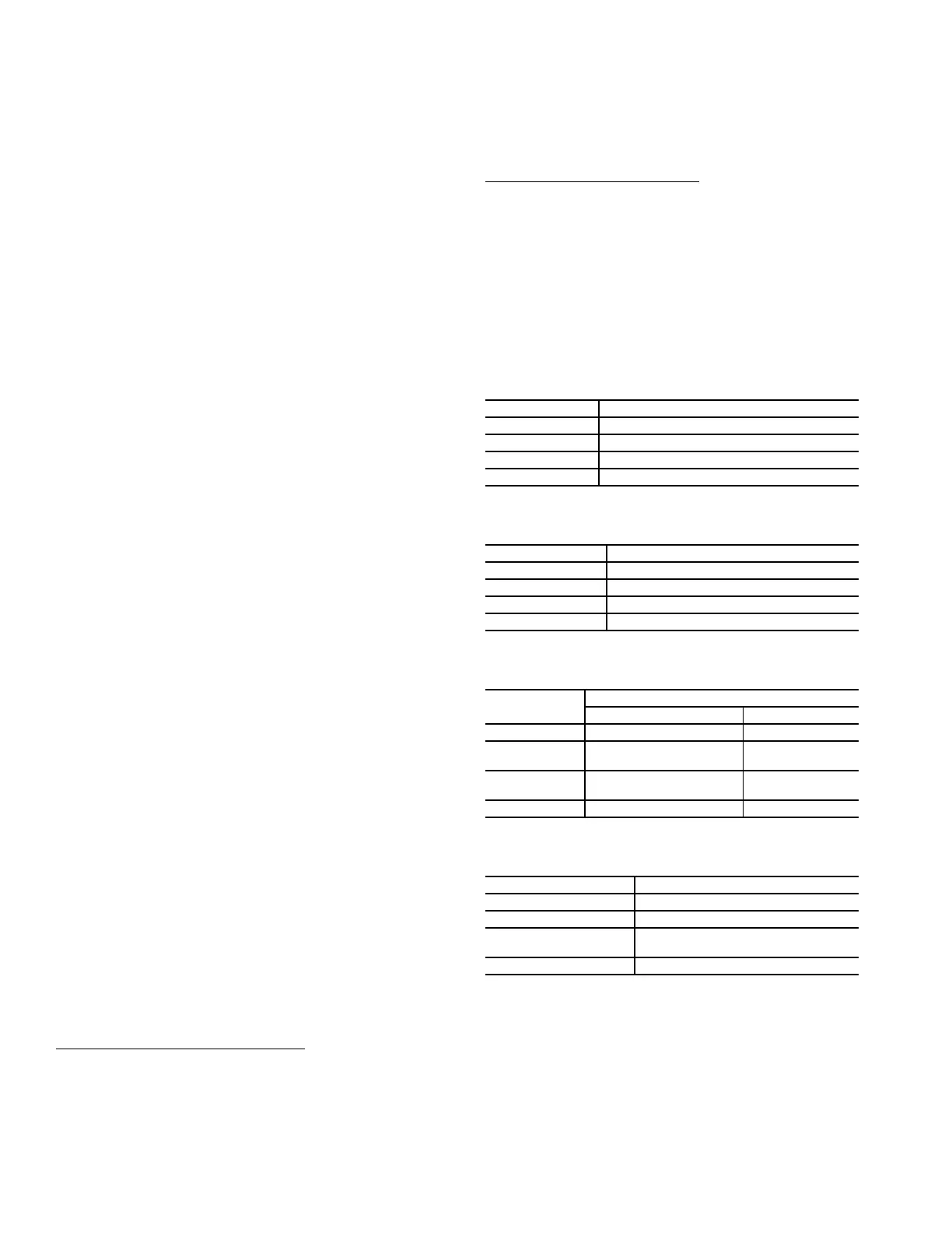
Table 38A — Outdoor Fan Level Transitions
without Humidi-MiZer System
Table 38B — Outdoor Fan Level Transitions
with Humidi-Mizer System
Table 39A — Fan Level Control of Outdoor Fan
Contactors (1, 2, 3) without Humidi-MiZer System
Table 39B — Fan Level Control of Outdoor Fan
Contactors (1 and 2) with Humidi-Mizer System
Gas Heating (48PG Units) — For 48PG units, the
heat type configuration Configuration
→
HEAT
→
HT.TY will
be factory set to a value of 1.
Heat will not operate if the outdoor temperature is
greater than the value configured for the heat lockout tempera-
ture, Configuration
→
HEAT
→
HT.LO. Minimum on-time,
Configuration
→
HEAT
→
MRT.H, and minimum off-time,
Configuration
→
HEAT
→
MOT.H, timeguards apply to both
stages of heating. Factory default values are 2 minutes On and
2 minutes Off. The IGC minimum on-time of 1 minute will be
followed even if MRT.H is lower and during Service Test.
FAN LEVEL OUTDOOR TEMPERATURE (F)
Level 2 On 55 (size 20), 45 (sizes 24, 28)
Level 2 Off 50 (size 20), 40 (sizes 24, 28)
Level 3 On 65
Level 3 Off 55
FAN LEVEL OUTDOOR TEMPERATURE (F)
Level 2 On 68 (size 20), 61 (size 24 and 28)
Level 2 Off 57
Level 3 On 88 (size 20), 68 (size 24 and 28)
Level 3 Off 78 (size 20), 62 (size 24 and 28)
FAN LEVEL
CIRCUIT
AB
0 ——
1
1 (20, 24)
1, 3 (28)
3
2
1, 2 (20)
2 (24, 28)
2, 3(20)
2 (24, 28)
3 1, 2 (20, 24) 1, 2, 3 (28) 2, 3
FAN LEVEL CIRCUITS A and B
0 —
1 1
2
1, 2 (20)
2 (24-28)
3 1, 2
 Loading...


