49
Indoor Air Quality (IAQ) — The ComfortLink™ con-
trol has the capability for several methods of demand ventila-
tion control. Indoor air quality is typically measured using a
CO
2
sensor whose measurements are displayed in parts per mil-
lion (ppm). Outdoor air quality may be measured with a CO
2
sensor for indoor-outdoor differential demand ventilation
control, or with other sensor types for the outdoor air lockout
function. The factory-installed indoor air quality CO
2
sensor is
mounted in the return section. A field-installed indoor air
quality CO
2
sensor may be mounted in the return or directly in
the occupied space, per job requirements. The indoor air quality
modes of operation can be affected by configurations for indoor
air quality sensor (Configuration
→
AIR.Q
→
IA.CF), indoor air
quality switch (Configuration
→
AIR.Q
→
II.CF), outdoor air
quality sensor (Configuration
→
AIR.Q
→
OA.CF) and other
related fan and limit configurations as described below.
IAQ (Analog Input) — The ComfortLink™ control is config-
ured for indoor air quality sensors which provide 4 to
20 mA for 0 to 2000 ppm. If a sensor has a different range,
the ppm display range must be reconfigured by entering new
values for Configuration
→
AIR.Q
→
I.4M and Configura-
tion
→
AIR.Q
→
I.20M.
IA.CF
= 0 (No IAQ) — IA.CF = 0 signifies that there is
no IAQ sensor installed. The damper will operate at the
Configuration
→
AIR.Q
→
EC.MN position when the space is
occupied and the indoor fan is on.
IA.CF
= 1 (DCV) — When IA.CF = 1, the IAQ algorithm is
set for Demand Control Ventilation (DCV). During DCV, the
damper modulates between two user configurations depending
upon the relationship between the IAQ and the Outdoor Air
Quality (OAQ). The lower of these two positions is referred to
as the Minimum IAQ Damper Position (Configuration
→
AIR.Q
→
AQ.MN) while the higher is referred to as Econo-
mizer Minimum Position (EC.MN). The AQ.MN should be set
to an economizer position that brings in enough fresh air to
remove contaminants and CO
2
generated by sources other than
people. The EC.MN should be set to an economizer position
that brings in enough fresh air to remove contaminants and
CO
2
generated by all sources including people. The EC.MN
value is the design value for maximum occupancy.
The ComfortLink control will begin to open the damper
from the AQ.MN position when the IAQ level begins to exceed
the Outdoor Air Quality (OAQ) level by a configurable
amount. This amount is referred to as AQ Differential Low
(Configuration
→
AIR.Q
→
AQD.L). When the differential
between IAQ and OAQ reaches AQ Differential High
(Configuration
→
AIR.Q
→
AQD.H), the economizer position
will be EC.MN. When the IAQ/OAQ differential is between
AQD.L and AQD.H, the control will modulate the damper
between AQ.MN and EC.MN in a linear manner as shown in
Fig. 11. The damper position will never exceed the bounds
specified by AQ.MN and EC.MN during IAQ control.
IA.CF =
2 (Override IAQ) — When IA.CF = 2, the IAQ
algorithm maintains the damper at Configuration
→
AIR.Q
→
EC.MN until the override condition triggers. The
override triggers when the IAQ/OAQ differential is greater
than Configuration
→
AIR.Q
→
AQD.H. The override position
is Configuration
→
AIR.Q
→
OVR.P (Economizer Override
Position). The economizer position will return to EC.MN
when the IAQ/OAQ differential is less than Configuration
→
AIR.Q
→
AQD.L.
The Override algorithm will operate whenever the building
is occupied and the indoor fan is operating or whenever the
IAQ algorithm has caused the indoor fan to operate. The
configuration IA.FN determines whether or not the IAQ algo-
rithm can turn on the indoor fan.
If the indoor fan is not operating, the economizer position
will be zero. If the override is not active and the building
is unoccupied, the economizer position will be zero.
The damper position may exceed Configuration
→
AIR.Q
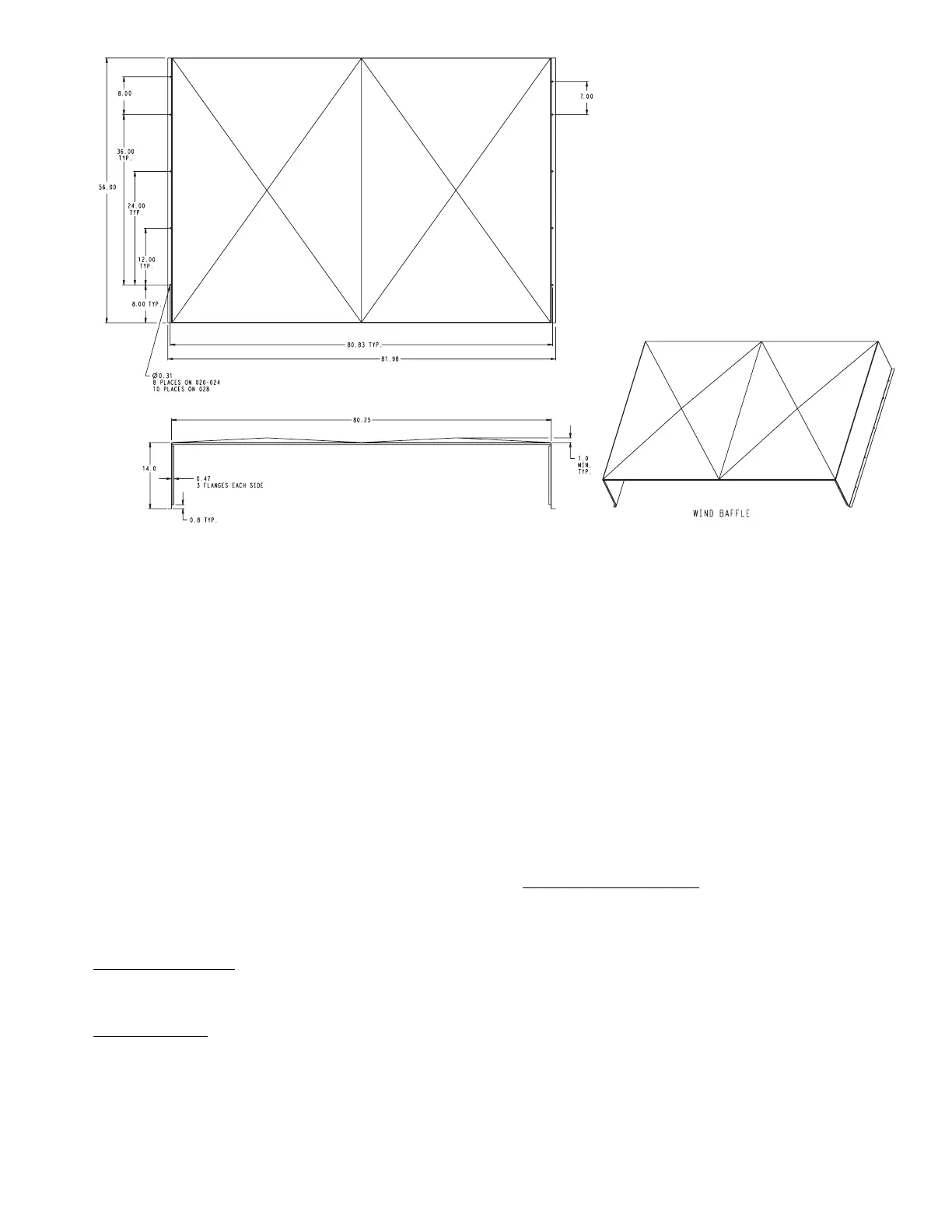
Fig. 10 — Wind Baffle Dimensions
a48-8226
 Loading...


