64
If a more accurate check is required, unit must be shut down
and thermistor removed and checked at a known temperature
(freezing point or boiling point of water) using either voltage
drop measured across thermistor at the J8 terminal, or by deter-
mining the resistance with unit shut down and thermistor
disconnected from J8. Compare the values determined with the
value read by the control in the Temperatures mode using the
Scrolling Marquee display.
SENSOR TRIM — Corrective offsets can be applied to the
space temperature and the supply air temperature sensor
readings. These corrections are set in the Configuration
→
TRIM menu for the display, or in the Maintenance
→
TRIM
table for CCN. See the Indoor Air Quality section for available
adjustments to IAQ and OAQ sensor readings. The space
temperature may be corrected by entering either a calibration
temperature value in SPT.C, or an offset temperature value in
SPT.T. The supply-air temperature may be corrected by enter-
ing either a calibration temperature value in SAT.C, or an offset
temperature value in SAT.T. Temperature corrections should
only be made if sensor readings are compared to an accurate
reference temperature measurement device.
Transducer Troubleshooting — The electronic con-
trol uses suction pressure transducers to measure the suction
pressure of the refrigerant circuits. The pressure/voltage char-
acteristics of these transducers are in shown in Table 52. The
accuracy of these transducers can be verified by connecting
an accurate pressure gage to the second refrigerant port in the
suction line.
Forcing Inputs and Outputs — Many variables may
have their value forced through CCN or directly at the local
display. This can be useful during diagnostic testing and also
during operation, typically as part of an advanced third party
control scheme. Input and output points that may be forced are
indicated as ‘forcible’ in the write status column of the display
and CCN tables.
If the user needs to force a variable, follow the same process
as when editing a configuration parameter. A forced variable
will be displayed on the Scrolling Marquee with a blinking
period “.” following its value. A forced value on Navigator™
accessory is indicated with a blinking “f”. A forced value on
CCN devices is indicated with “Control” if forced at the unit
display, or “Supervisor” if forced via CCN. To remove a local
force with the Scrolling Marquee, select the point with the
ENTER key and then press the up-arrow and down-arrow keys
simultaneously.
NOTE: In the case of a control power reset, any force in effect
at the time of power reset will be cleared.
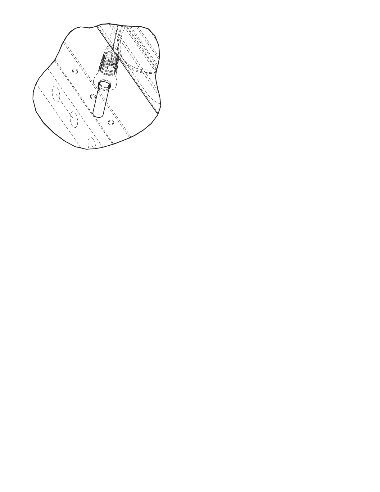
Fig. 13 — SAT and OAT Thermistor Mounting
a48-7823
 Loading...


