6
START-UP
Use the following information and Start-Up Checklist on
page CL-1 to check out unit PRIOR to start-up.
Unit Preparation — Check that unit has been installed in
accordance with these installation instructions and all applica-
ble codes.
Compressor Mounting — Compressors are internally
spring mounted. Do not loosen or remove compressor hold-
down bolts.
Refrigerant Service Ports — Each independent re-
frigerant system has a total of 3 Schrader-type service gage
ports per circuit. One port is located on the suction line, one on
the compressor discharge line, and one on the liquid line. Be
sure that caps on the ports are tight.
Crankcase Heater(s) — Crankcase heaters are ener-
gized as long as there is power to the unit and the compressor is
not operating.
Compressor Rotation
It is important to be certain the compressors are rotating in
the proper direction. To determine whether or not compressors
are rotating in the proper direction, use a phase-rotation meter
on the unit input power to check for L1-L2-L3 or clockwise ro-
tation or use the Service Test mode to energize a compressor. If
the compressor is rotating in the wrong direction, the controls
will stop the compressor and display alarm for “Circuit x Fail-
ure to Pressurize,” where x is the corresponding A or B com-
pressor circuit.
NOTE: Indoor or outdoor fan rotation direction may not indi-
cate proper input power phase sequence, as some 3-phase units
use single-phase fan motors.
To correct the wrong compressor rotation direction, perform
the following procedure:
1. Turn off power to the unit and lock out the power.
2. Switch any two of the incoming unit power leads.
3. Turn on power to the unit.
4. Verify corrected compressor rotation.
Internal Wiring — Check all electrical connections in
unit control boxes; tighten as required.
Subcooler Heat Exchanger (SHX) — The subcool-
er heat exchanger adds approximately 10 to 15° F of sub-
cooling to the system. Check all valves and TXV.
Evaporator Fan — Fan belt and variable pulleys are
factory-installed. See Tables 3-26 for fan performance data. Be
sure that fans rotate in the proper direction. See Tables 27 and
28 for air quantity limits. See Tables 29 and 30 for evaporator
fan motor specifications. See Tables 31 and 32 for accessory
FIOP static pressure. See Tables 33 and 34 for fan rpm at
various motor pulley settings. To alter fan performance, see
Evaporator Fan Performance Adjustment section on page 87.
Condenser Fans and Motors — Condenser fans and
motors are factory set. Refer to Condenser-Fan Adjustment
section (page 88) as required.
Return-Air Filters — Check that correct filters are in-
stalled in filter tracks (see Physical Data table in Installation
Instructions). Do not operate unit without return-air filters.
NOTE: For units with 4-in. filter option, units are shipped with
standard 2-in. filters. To install 4-in. filters, the filter spacers
must be removed.
Outdoor-Air Inlet Screens — Outdoor-air inlet screens
must be in place before operating unit.
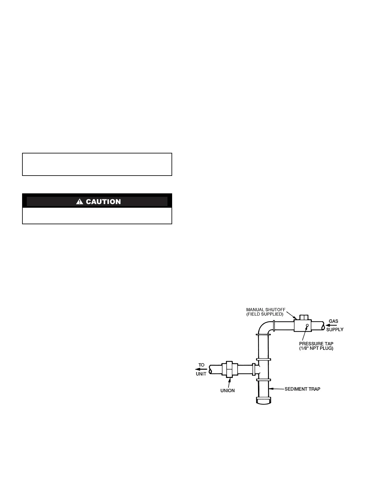
Gas Heat (48PG Only) — Verify gas pressures before
turning on heat as follows:
1. Turn off field-supplied manual gas stop, located external
to unit.
2. Connect pressure gage to supply gas tap, located on field-
supplied manual shutoff valve (see Fig. 4).
3. Connect pressure gage to manifold pressure tap.
4. Turn on field-supplied manual gas stop. Enter Service
Test mode by setting TEST to “YES” using the Scrolling
Marquee display. Temporarily install the jumper wire
between “R” and “W1” on TB2. Use the Service Test
feature to set HT.1 to ON (first stage of heat) using the
Scrolling Marquee.
5. After the unit has run for several minutes, verify the sup-
ply gas pressure is between 5.5 in. wg to 13.0 in. wg, and
the manifold pressure is 2.95 in. wg on horizontal dis-
charge applications and 3.00 on vertical discharge appli-
cations. If manifold pressure must be adjusted, refer to
Gas Valve Adjustment section.
NOTE: Supply gas pressure must not exceed 13.0 in. wg.
6. Set HT.1 to OFF using Scrolling Marquee.
7. Remove jumper wire if the unit will be operating under
thermostat mode. The jumper must remain if a space tem-
perature sensor (T-55, T-56, or T-58) will control the unit.
8. Exit Service Test mode by setting TEST to “NO” using
the Scrolling Marquee.
IMPORTANT: Unit power must be on for 24 hours prior
to start-up. Otherwise, damage to compressor may
result.
Improper wiring will cause compressor stoppage and alarm.
Correct wiring by switching leads as indicated below.
Fig. 4 — Field Gas Piping
a48-7569
 Loading...


