90
The TXV (thermostatic expansion valve) is set to maintain
between 10 and 15 degrees of superheat at the compressors.
The valves are factory set and cannot be adjusted. Do not use
an R-22 TXV.
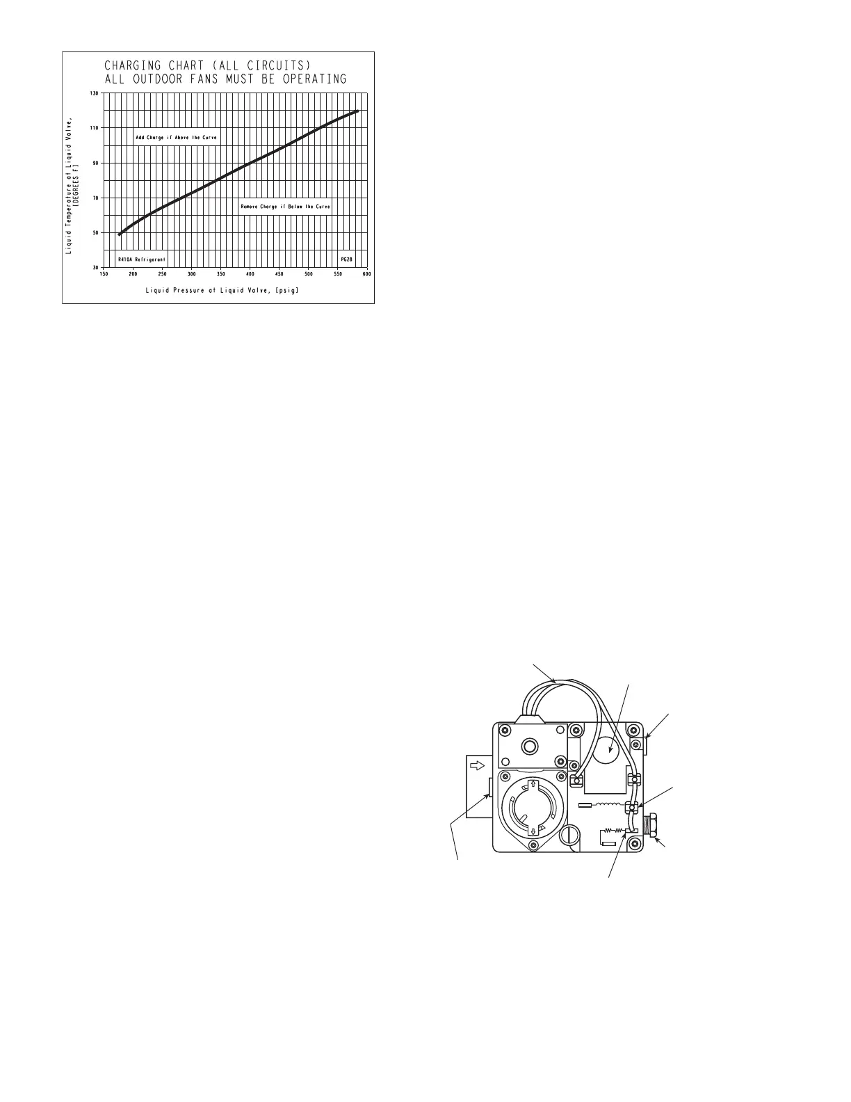
NOTE: All circuits must be running in normal cooling mode.
Indoor airflow must be within specified air quantity limits for
cooling (see Tables 27 and 28). All outdoor fans must be on
and running at high speed. If outdoor temperature is low, this
may require a temporary change in unit wiring.
TO USE THE COOLING CHARGING CHARTS, UNITS
WITH HUMIDI-MIZER ADAPTIVE DEHUMIDIFICA-
TION SYSTEM
NOTE: All circuits must be running in normal cooling mode.
Indoor airflow must be within specified air quantity limits for
cooling (see Tables 27 and 28). All outdoor fans must be on
and running at high speed. Use the Cooling Service Test Out-
door Fan function (Service Test
→
COOL
→
OF.OV) to start all
outdoor fans. If the outdoor temperature is low, the Motormas-
ter® outdoor fan control device may need to be temporarily
bypassed by rewiring the power leads to obtain full speed.
Be sure unit is in normal cooling mode by checking that the
RH2 solenoid coil(s) and the CRC relay are deenergized
(control outputs off). Adjust charge per the charging charts as
described in the To Use The Cooling Charging Charts,
Standard Unit section on page 89. Switch system to run in the
dehumidification mode for 5 minutes. Dehumidification mode
is when the RH2 solenoid coil(s) and the CRC relay are
energized. Switch back to cooling mode to recheck pressures
and temperatures on the charging chart and adjust charge if
necessary. If charge adjustment is necessary, then repeat the
steps in this paragraph until no charge adjustment is necessary.
When no more charge adjustment is necessary after switching
from Dehumidification mode back to Cooling mode, then
charge adjustment procedure is complete. Remove jumper
from the outdoor motor speed controller.
PURON® REFRIGERANT — Puron refrigerant operates at
50 to 70 percent higher pressures than R-22. Be sure that
servicing equipment and replacement components are designed
to operate with Puron refrigerant. Do not mix with components
that have been used with other refrigerants. Puron refrigerant,
as with other HFCs, is only compatible with POE oils.
Recovery cylinder service pressure rating must be 400 psig.
Puron systems should be charged with liquid refrigerant. Use a
commercial-type metering device in the manifold hose. Mani-
fold sets should be 750 psig high-side and 200 psig low-side
with 520 psig low-side retard. Use hoses with 750 psig service
pressure rating. Leak detectors should be designed to detect
HFC refrigerant.
Gas Valve Adjustment (48PG Only)
NATURAL GAS — The gas valve opens and closes in re-
sponse to the thermostat or limit control.
When power is supplied to valve terminals W2 (High Fire)
and C1, the main valve opens to its preset position.
The regular factory setting is stamped on the valve body.
The setting is 3.00 in. wg for vertical supply/discharge units.
The setting is 2.95 in. wg for horizontal supply/discharge units.
To adjust regulator:
1. Set unit at setting for no call for heat.
2. Turn main gas valve to OFF position.
3. Remove
1
/
8
-in. pipe plug from manifold or gas valve
pressure tap connection. Install a suitable pressure-
measuring device.
4. Set main gas valve to ON position.
5. Set thermostat at setting to call for heat.
6. Remove screw cap covering regulator adjustment screw
(See Fig. 46).
7. Turn adjustment screw clockwise to increase pressure or
counterclockwise to decrease pressure.
8. Once desired pressure is established, set unit setting
for no call for heat, turn off main gas valve, remove
pressure-measuring device, and replace
1
/
8
-in. pipe
plug and screw cap.
High Altitude (48PG Only) — For high altitude appli-
cations greater than 2000 ft the heat input rate should be
reduced. The higher the altitude is above sea level, the less
oxygen is in the air. See Table 58 for orifice sizing. A high alti-
tude kit is available to convert unit for altitudes up to 7,000 ft.
Fig. 45 — Charging Chart — 48/50PG28 — Standard
Unit and Unit with Humidi-MiZer™ System
a48-7784
OFF
ON
W-1
W-2
D-1
D-2
C1
C2
PILOT
ADJ.
INLET PRESSURE TAP
(PLUGGED)
1/8 - 27 N.P.T. THDS.
2 LEADS, #18 WIRE 1/32 INSULATION,
600V. MAX., 105°C
REGULATOR
ADJUSTMENT SCREW
(REMOVE COVER)
OUTLET PRESSURE
TAP (PLUGGED)
1/8-27 N.P.T. THDS.
PILOT CONNECTION
FOR 1/4” O.D. TUBING
(PLUGGED)
RECEPTACLE AND
TAB COMBINATION
TERMINAL
RECEPTACLE TERMINAL
Fig. 46 — Gas Valve (48PG Only)
a48-5717
 Loading...


