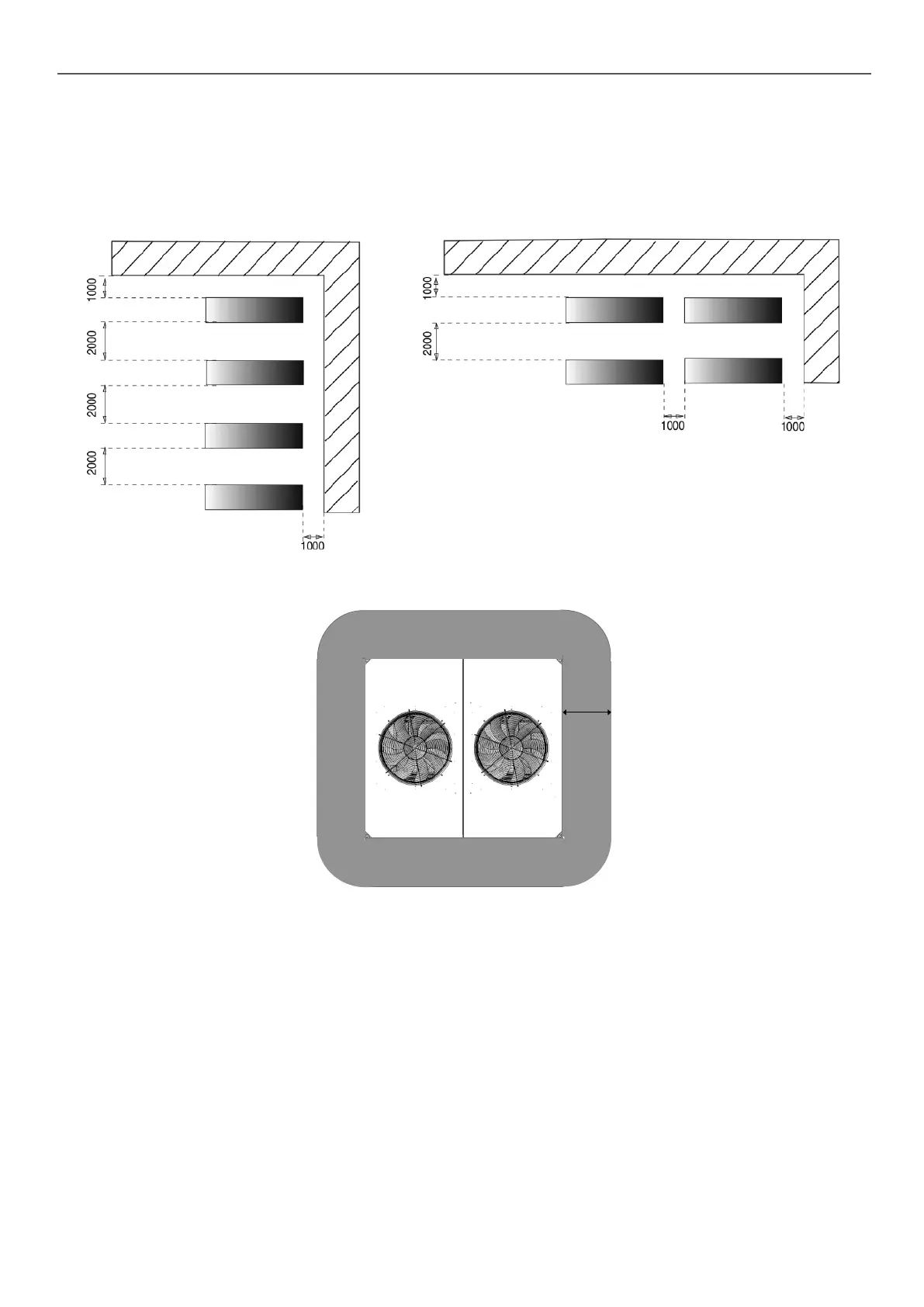
4.5 - Free spaces and installing several units
In multiple-chiller installations (maximum of four units), the free space between the sides of the units should be increased
to between 1000 and 2000 mm.
The height of the solid surface must not exceed 2 m.
NOTE: If the walls are higher than 2 m, contact the factory
Solid wall Solid wall
4.6 - Positioning of ATEX zones around the unit
Electrics box side
60 cm
Due to the nature of the refrigerant in these units (A2L uid), ATEX zones have been identied and positioned around the units, as
shown in the diagram opposite.
The ATEX zones, as dened, must only be entered by suitably trained personnel equipped with the appropriate detection
material and tools for working in an ATEX zone.
ATEX zone 2 is involved.
The machines are designed to be installed outdoors, in a free eld-type, ventilated area.
As the refrigerant used is heavier than air, it is essential that installations joined to the unit prevent the retention of refrigerant at the
lowest point in the event of a leak.
4 - DIMENSIONS, CLEARANCES, MINIMUM INSTALLATION DISTANCES
11
 Loading...