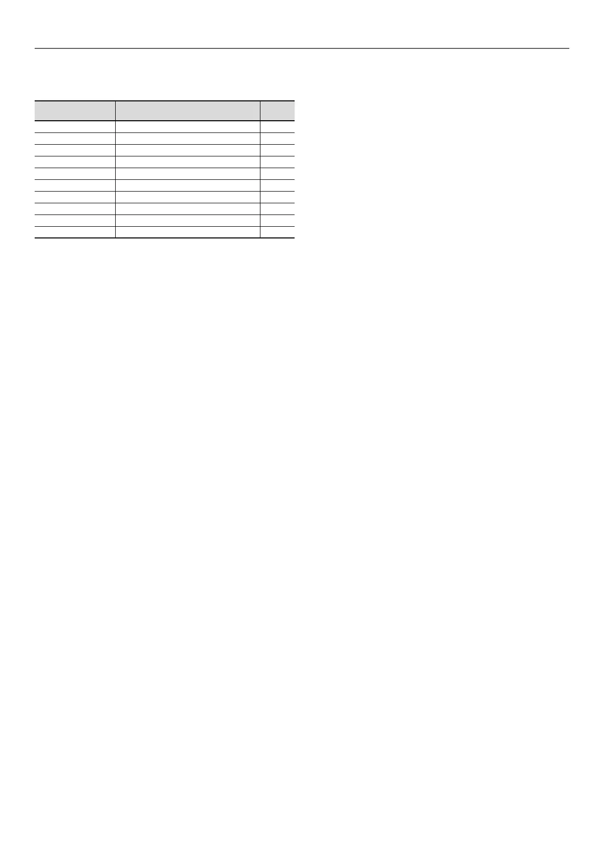
13.5 - Tightening torques for the main
fastenings
Screw type Use
Value
(N.m)
Compressor rail Compressor bracket 30
M10 nut BPHE* xing 18
M10 nut Compressor assembly 30
M16 nut Compressor mounting 30
Oil nut Oil equalisation line 75
Taptite screw M6 Fan support 7
Taptite screw M8 Fan motor xing 13
M8 hex screw Impeller xing 18
Panel screw Panel part xing 4,2
M6 hex screw Stau collar 10
* BPHE = Brazed Plate Heat Exchanger
13.6 - Air heat exchanger
We recommend that coils are inspected regularly to check the
degree of fouling. This depends on the environment where the
unit is installed, in particular urban and industrial sites, and for
units installed near trees that shed their leaves.
Recommendations for maintenance and cleaning of air heat
exchangers:
- Regularly cleaning the coil surface is essential for correct
unit operation.
- Eliminating contamination and removal of harmful residue
will increase the operating life of the coils and the unit.
- The maintenance and cleaning procedures below are part of
the regular maintenance to increase the operating life of coils.
- Specic recommendation in case of snow: For long term
storage, regularly check that no snow has accumulated on
the coil.
Specic RB equipped with MCHEs:
- Clean the surface of the coil by spraying the coil regularly
and uniformly from bottom to top, orienting the water jet at
right angles to the surface. Do not exceed a water pressure
of 6200 kPa (62 bar) or an angle of 45° related to the coil.
The nozzle must be at least 300 mm away from the coil
surface.
- Clean and scrub the entire connection with a exible Nylon,
PolyPro® or Tynex® brush and low pressure tap water.
Level 1 cleaning:
- Remove all foreign objects or debris attached to the surface of the
coil or wedged between the casing and the supports
- Use a low pressure dry air jet to remove all traces of dust
from the coil.
Level 2 cleaning:
- Carry out the level 1 cleaning operations.
- Clean the coil using suitable products.
Use appropriate PPE including safety glasses and/or mask,
waterproof clothes and safety gloves. It is recommended to
wear clothing that covers the whole body.
Specic products approved by the manufacturer for cleaning
coils are available from the manufacturer's spare parts
network. The use of any other product is strictly prohibited.
After the cleaning product is applied, rinsing with water is
mandatory (see manufacturer's standard RW01-25).
IMPORTANT:
Never use a pressure water spray without a large diuser.
Concentrated and/or rotating water jets are strictly forbidden.
Never use a uid with a temperature above 45 °C to clean the
air heat exchangers.
Correct and frequent cleaning (approximately every three
months) will prevent two thirds of corrosion problems. Protect
the electrics box during cleaning operations.
13.7 - Water type heat exchanger
Check that:
- The insulation has not been detached or torn during
operations,
- The heaters and probes are operating and correctly
positioned in their support,
- The water-side connections are clean and show no sign of
leakage,
- The periodic inspections required by local regulations have
been carried out
13.8 - Frequency inverter
IMPORTANT: Before any work on the variable frequency drive,
ensure that the circuit is isolated and there is no voltage
present (reminder: The capacitors take approximately 5
minutes to discharge once the circuit breaker has been
opened). Only appropriately qualified personnel are
authorised to work on the variable frequency drive.
In case of any alarm or persistent problem related to the variable
frequency drive, contact the manufacturer's service department.
The variable frequency drives tted on the units do not require a
dielectric test, even if being replaced: they are systematically
checked before delivery. Moreover, the ltering components
installed in the variable frequency drive can falsify the measurement
and may even be damaged. If there is a need to test the insulation
of the unit components (fan motors and pumps, cables, etc.), the
variable frequency drive must be disconnected from the power
circuit.
13 - STANDARD MAINTENANCE
48
 Loading...