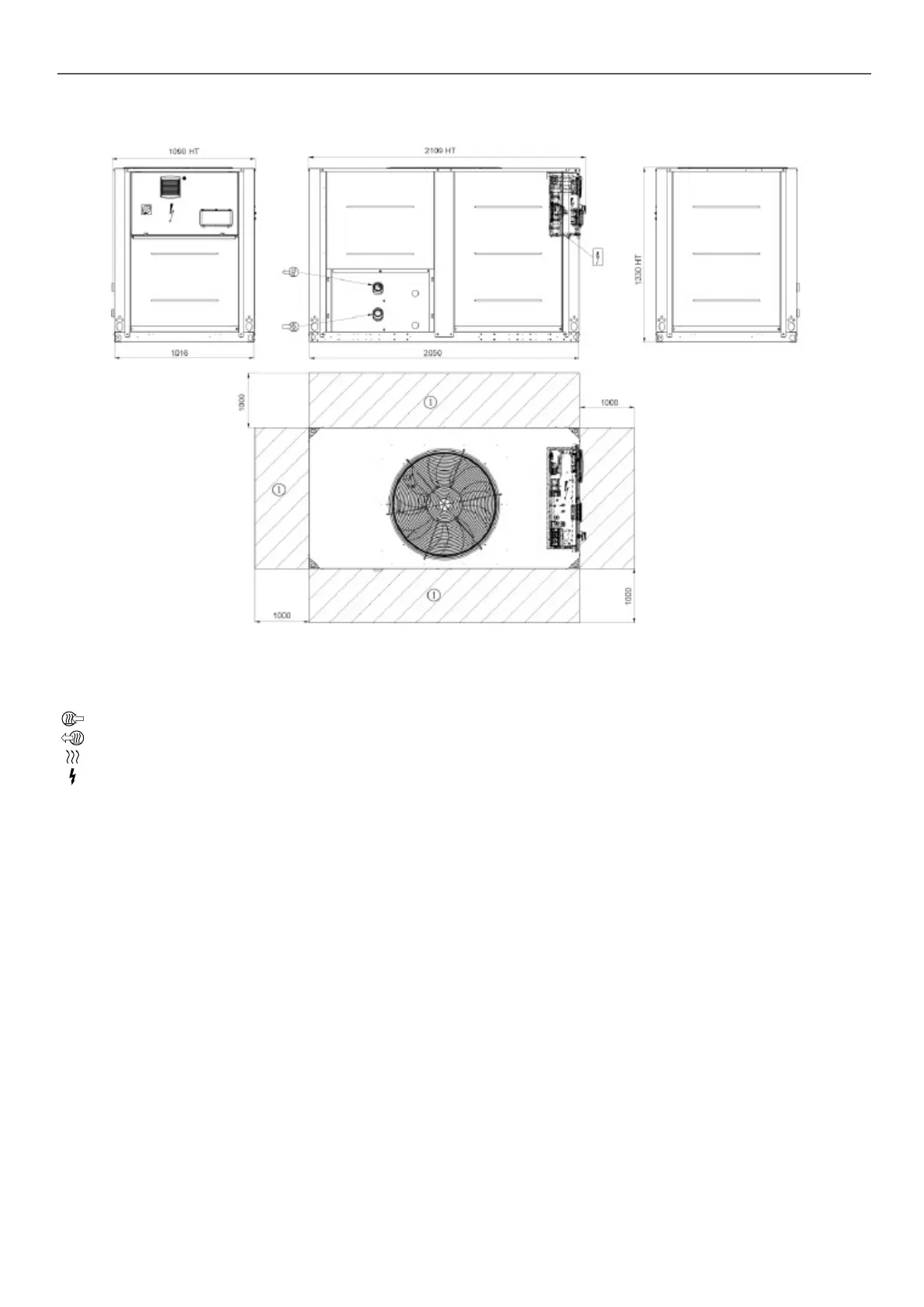
4 - DIMENSIONS, CLEARANCES, MINIMUM INSTALLATION DISTANCES
4.1 - 30RB/30RQ 040R-080R, units with and without hydraulic module
Key:
All dimensions are given in mm.
NOTE: Non-contractual drawings.
When designing a system, refer to the certied dimensional
drawings provided with the unit or available on request.
Refer to the certied dimensional drawings for the location
of xing points, weight distribution and coordinates of the
centre of gravity, hydraulic and electrical connections.
B
Clearances required for maintenance and air ow
C
Clearance recommended for coil removal
Water inlet
Water outlet
Air outlet, do not obstruct
Control box
7
 Loading...