8.5.1 - Hydraulic circuit cleaning procedure
Before proceeding, it is advisable to remove any possible
contamination from the hydraulic circuit.
• Start up the unit pump by using the override command.
• Set the frequency to the maximum value to generate a
higher ow rate.
• If there is a ‘‘Maximum fow exceeded’’ alarm, reduce the
frequency until an acceptable value is reached.
• Read the value of the ow on the user interface.
• Let the pump run for 2 hours continuously to ush the
system's hydraulic circuit (presence of contaminating
solids).
• Perform another reading of the ow and compare this value
with the initial value. A reducing value of the ow indicates
that the lters on the system need to be removed and
cleaned. In this case, close the shut-o valves on the water
inlet and outlet (item 19) and remove the lters (items 12
and 1) after draining the hydraulic part of the unit (item 6).
• Remove the air from the circuit (items 5 and 14).
• Repeat until all fouling is removed from the lter.
8.5.2 - Procedure for controlling the pressure
dierential
Setpoint
Once the circuit is cleaned, place the hydraulic circuit in the
conguration for which the unit selection was performed generally
(all valves open and all cooling coils active). Read the value of
the !ow on the user interface and compare it with the theoretical
value of the range:
• If the value of the ow is greater than the specied value,
reduce the pressure differential setpoint on the user
interface to reduce the value of the ow.
• If the value of the ow is lower to the specied value,
increase the pressure dierential setpoint on the user
interface to increase the value of the ow.
Repeat until the design pressure drop / ow rate is achieved.
Stop the forced operation of the pump and proceed to the
conguration of the unit for the required control mode.
Modify the control parameters:
- Set water ow control to ‘pressure dierential’
- Set the value of the required dierential pressure
By default, the unit is factory congured at the minimum speed
(frequency: 50 Hz).
NOTES:
If during controlling, the low or high frequency limits are
reached before reaching the specied ow, keep the pressure
dierential value to its lower or higher limit to enter in the
control parameters.
If the user already knows the pressure dierential value to
be maintained at the unit outlet, this may be entered directly
as a parameter. However, the hydraulic circuit cleaning
sequence must not be omitted.
8.6 - Units with hydraulic module and variable-
speed pump - temperature dierence control
The temperature sensors at the heat exchanger inlet and outlet
(items 8 and 9 in the typical hydraulic circuit diagram) are used
as means of control.
The system reads the measured temperature values, calculates
the corresponding temperature dierence, compares it with the
user-selected setpoint value and modulates the pump speed as
necessary:
• If a higher delta T value than the set point is measured, the
ow rate is increased.
• If a lower delta T value than the set point is measured, the ow
rate is decreased.
This ow rate variation is realised, observing the minimum and
maximum admissible unit ow rates as well as the minimum and
maximum pump supply frequency values.
The delta T value maintained can in certain cases be dierent from
the set point value:
• If the set point value is too high (achieved for a lower ow rate
than the minimum value or a lower frequency than the
minimum value), the system settles at the minimum ow rate
or minimum frequency and this results in a lower delta T value
than the set point.
• If the set point value is too low (achieved for a higher ow rate
that the maximum value or a higher frequency than the
maximum value), the system settles at the maximum ow rate
or maximum frequency and this results in a higher delta T
value than the set point.
Contact Carrier Service to discuss the implementation of the
procedures set out below.
8.6.1 - Hydraulic circuit cleaning procedure
Refer to the procedure for cleaning the hydraulic circuit from chapter
8.3.1
8.6.2 - Procedure for adjusting the Delta T° setpoint
Once the circuit is cleaned, stop the forced start of the pump and
proceed to the conguration of the unit for the required control mode.
Modify the control parameters:
- Water ow rate control method (temperature dierential)
- Set the value of the required dierential temperature.
By default, the unit is factory congured at the minimum speed
(frequency: 50 Hz).
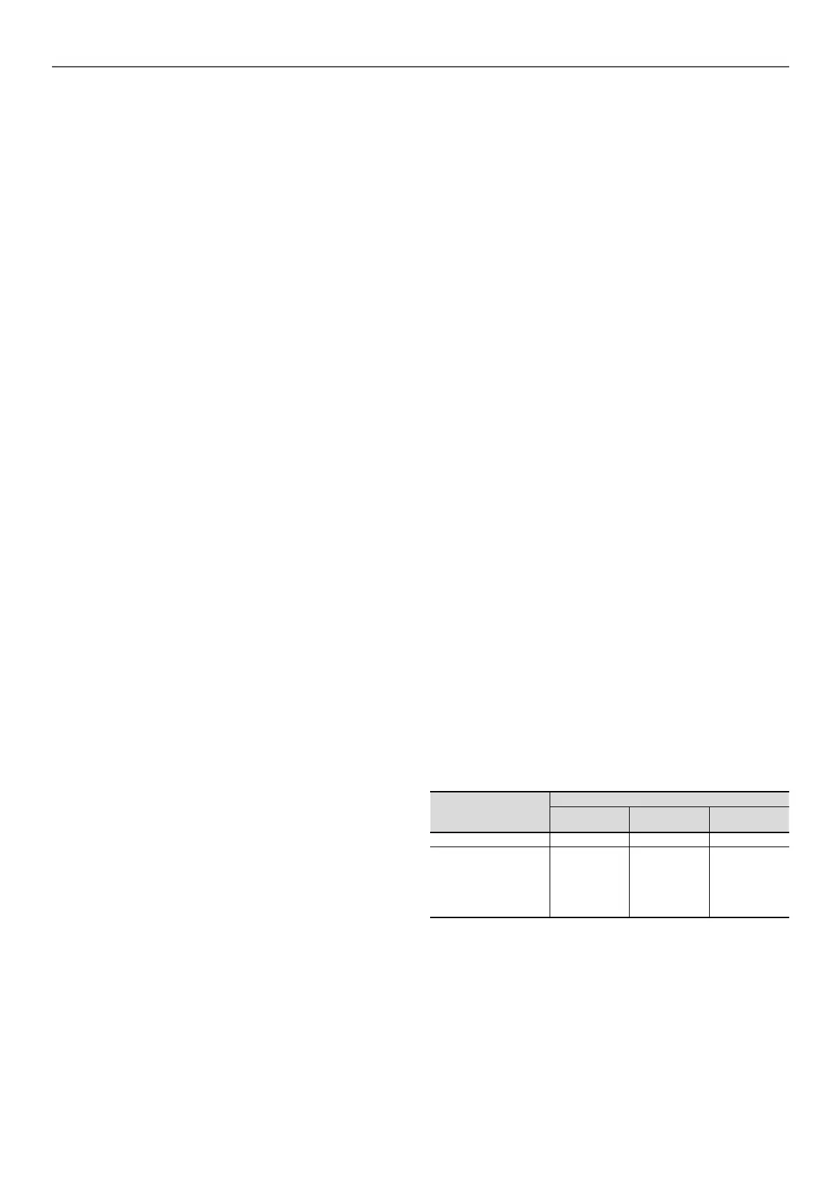
Combination of options for the periods when the unit is in
standby mode.
Ambient unit
temperature range
Product
without
option 116
With option
116
With option
307
> 0 °C to 51 °C - -
-20 °C to 0 °C
Option 41
or
Suitable
antifreeze
solution (such
as glycol)
Option 42
(1)
or
Suitable
antifreeze
solution (such
as glycol)
(1)
Option 42B
(1)
or
Suitable
antifreeze
solution (such
as glycol)
(1)
(1) Allow the pumps to circulate. If there is a valve, install a bypass (see diagram
for winter position).
8 - WATER CONNECTIONS
29
 Loading...