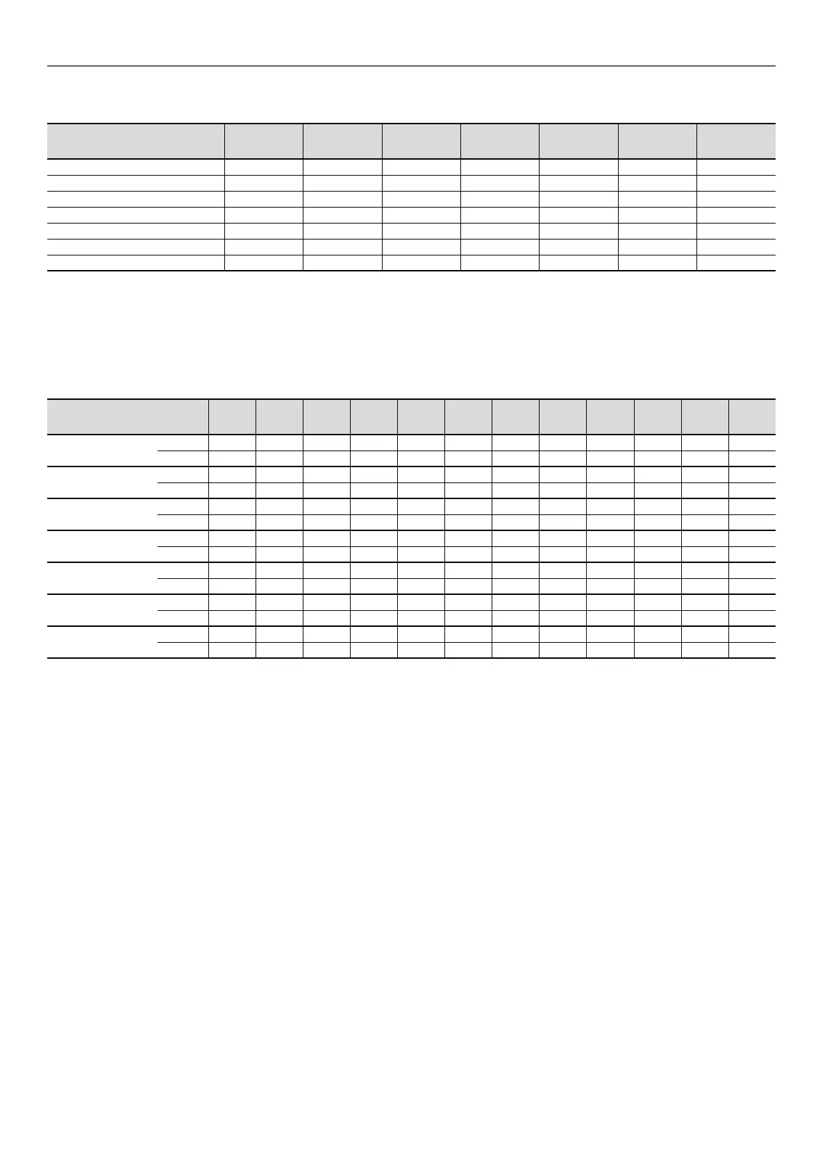
5.5 - Electrical data notes for the compressors
Compressor I Nom
(1)
I Max (Un)
(2)
I Max
(Un - 10%)
(3)
LRA A
(4)
I start
option 25 (A)
(5)
Cos
Phi nom.
(6)
Cos
Phi Max. ()
(7)
DSF090 11,5 15,8 17 98 63,7 0,78 0,83
DSF100 13,4 17 18,2 98 63,7 0,79 0,84
DSF115 16,2 19,9 20,5 142 92,3 0,78 0,83
DSF130 15,3 21,6 23,1 142 92,3 0,8 0,86
DSF155 20,2 24,5 26,2 147 95,6 0,81 0,86
DSF175 23,5 27,6 29,7 158 102,7 0,83 0,87
DSF200 24,3 31,1 33,3 197 128,1 0,8 0,85
(1) Nominal current draw (A) under standard Eurovent conditions (see denition of conditions under nominal unit current draw)
(2) Maximum operating current
(3) Maximum compressor operating current, limited by the unit (current given for maximum capacity at 360 V)
(4) Locked rotor current at nominal voltage, corresponding to the direct start-up current
(5) Locked rotor current with electronic starter at nominal voltage
(6) Values recorded under standard Eurovent conditions: Evaporator water outlet/inlet = 12 °C/7 °C. Condenser water outlet/inlet = 30 °C/35 °C.
(7) Value recorded at maximum capacity and nominal voltage
5.6 - Distribution of compressors per circuit
Compressor Circuit 040R 045R 050R 055R 060R 070R 080R 090R 100R 120R 140R 160R
DSF90
A 2
B
DSF100
A 2
B
DSF115
A 2 2
B
DSF130
A 2
B
DSF155
A 2 3 2
B 2
DSF175
A 2 3 2
B 2
DSF200
A 2
B
5 - PHYSICAL AND ELECTRICAL DATA FOR THE UNITS
16
 Loading...