ADJUSTING PID ROUTINES — The 30GX and 30HXC
head pressure control routines use PID (proportional inte-
gral derivative) loops to maintain a user-configurable head
pressure set point. Gain default values are located in the Serv-
ice function. See page 30. The current values can be read
under from the HSIO. The control calculates a new
fan speed (30GX) or water valve position (30HXC) every
5 seconds based on these gain values and an error term equal
to saturated condensing temperature minus head pressure set
point. If the control routine is not responding fast enough to
large changes (circuit starting, for example), increase the pro-
portional term.
When the routine is making too great a change to valve
position or fan speed, decrease the proportional term. To mini-
mize hunting, keep the integral term positive and as low as
possible. The default for the derivative term is zero. This
valve is used to control ‘‘droop,’’which is common in master/
submaster control schemes. The value should not need to be
changed.
Cooler and Condenser (30HXC) Pump Control
—
The 30GX and 30HX chillers can be configured for cooler
and condenser (30HXC) pump control. Inputs for a cooler
flow switch or interlock and condenser flow switch are also
provided.
COOLER PUMP CONTROL ( ) — The factory de-
fault setting for cooler pump control is ‘‘Not Controlled.’’
All chillers are enabled at the factory for cooler pump in-
terlock. See page 71 of Field Wiring section for wiring of
cooler flow switch and/or cooler pump interlock contacts.
Whether cooler pump control is enabled or not, the control
generates an alarm if this input does not close within one
minute after the unit switches to an occupied mode or the
cooler pump is turned on. See Alarms and Alerts section,
page 43 for a description of Alarms 53-55. If cooler pump
control is enabled, the control waits one minute and checks
the interlock or switch input before starting to determine if
cooling is needed. The cooler pump is turned on when the
chiller is in the occupied mode and turned off otherwise. The
cooler pump is turned on in either of two override condi-
tions: If the cooler freeze protection alarm has been gener-
ated, the cooler pump is turned on if not already running. If
a cooler heater is being used and has been on for more than
15 minutes during saturated suction freeze protection, the
cooler pump is turned on.
1
2
3
4
CONTROL
BOX
END
5
6
7
8
9
10
CONTROL
BOX
END
4
2
1
3
CONTROL
BOX
END
13 5 7
24 6 8
CONTROL
BOX
END
4
6
1
3
5
2
5
CONTROL
BOX
END
7911
12
6810
4
2
3
1
CONTROL
BOX
END
1
3
5
7
2
4
6
8
CONTROL
BOX
END
14
12
10
13
11
9
1
3
5
7
2
4
6
8
9
11
12
10
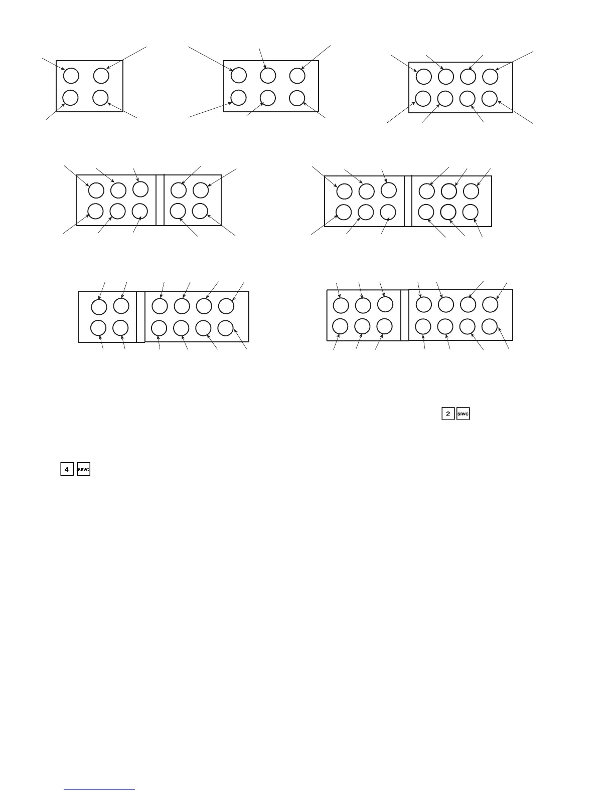
Fig. 5 — 30GX Condenser Fan Locations
30GX080-105 30GX106-125
30GX151, 161, 175, 205, 225 30GX176
30GX206, 226, 250
30GX136, 150, 160
30GX251, 265
10
 Loading...