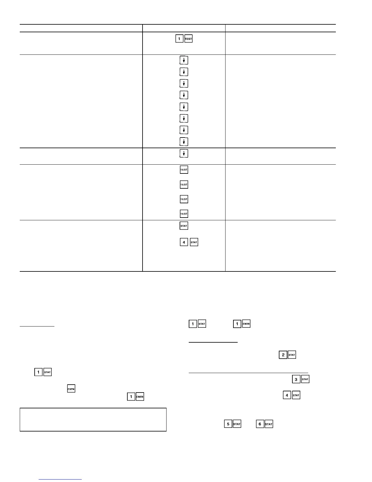
Table 9 — Accessing Functions and Subfunctions
OPERATION KEYPAD ENTRY DISPLAY RESPONSE
To access a function, press
subfunction no. and function
name key. Display shows sub-
function group.
Circuit A Discrete Outputs
Loader A1
Relay is OFF
To move to other elements,
scroll up or down using arrow keys.
Loader A2
Relay is OFF
Minimum Load Valve A
Relay is OFF
Circuit A Oil Heater
Relay is OFF
A1 Mtr. Cooling Solenoid
Relay is OFF
A2 Mtr. Cooling Solenoid
Relay is OFF
Circuit A Oil Pump
Relay is OFF
Oil Solenoid A1
Relay is OFF
Oil Solenoid A2
Relay is OFF
When the last element in a
subfunction has been displayed,
the first element is repeated.
Loader A1
Relay is OFF
To move to next subfunction
it is not necessary to use
subfunction number. Press
function name key to
advance display through all
subfunctions within a
function and then back
to the first.
Circuit B Discrete Outputs
Loader B1
Relay is OFF
Unit Discrete Outputs
Valves and Motor Master
Circuit A Discrete Outputs
To move to another function,
either depress function name
key for desired function
(display shows the first
subfunction),
or
Access a specific sub-
function by using the sub-
function number and the
function name key.
Alarms : xx
Reset Alarms : 1 <ENTER>
CIR. A DISCRETE OUTPUTS
STATUS FUNCTION — This function shows the rotating
display, current status of alarm and alert (diagnostic) codes,
capacity stages, operating modes, chilled water set point, all
measured system temperatures and pressures, analog inputs,
and switch inputs. Refer to Table 10 for a complete descrip-
tion of the function.
Alarms/Alerts — Alarms and alerts are messages that one
or more faults have been detected. The alarms and alerts in-
dicate failures that cause the unit to shut down, terminate an
option (such as reset) or result in the use of a default value
such as a set point. Refer to the Troubleshooting section for
more information.
Up to 10 alarms/alerts can be stored at once. To view them,
press . The control will display the current total
number of alarms/alerts. Use the arrow keys to scroll through
the list. Press the key when needed to view the full
description of an alarm or alert. Press to clear
all the alarms. See Table 11.
IMPORTANT: Do not clear the alarms without first
reviewing the full list and investigating and correcting
the cause of the alarms.
When an alarm or alert is stored in the display and the
machine automatically resets, the alarm/alert is deleted. Codes
for safeties which do not automatically reset are not deleted
until the problem is corrected and the machine is reset. To
clear manual reset alarms from the CPM modules, the reset
button on the HSIO bracket must be pressed. Next, switch
the LOR switch to OFF and back to Local or Remote
position (default alarm clearing method). Press
and then to clear the alarm from the PSIO
if the default LOR reset function has been disabled.
General Parameters — General operating parameters are
displayed including control mode, run status, CCN status,
and the 5 most current alarms. Press to display these
and the other values as shown in Table 10.
Circuit A and B Analog and Discrete Information — Circuit
A Analog Values can be viewed by pressing and scroll-
ing down to see current system operating conditions such as
pressures and temperatures. Pressing will bring up
Circuit A Discrete Inputs and Outputs. Scroll down to view
the On/Off status of the compressor(s), loaders, solenoids,
and pumps. Oil switch and feedback inputs are also dis-
played. Press and to view the identical ana-
log values and discrete inputs and outputs for Circuit B. See
Table 10 for a complete display.
16
 Loading...