EasyManua.ls Logo

Carrier Ecologic 30GX080-265 User Manual

Carrier Ecologic 30GX080-265
100 pages
To Next Page IconTo Next Page
To Previous Page IconTo Previous Page
Page #12 background imageLoading...
Page #12 background image
CONDENSER PUMP CONTROL ( ) Factory de-
faults for both condenser pump control and condenser flow
switch are set to ‘Not Controlled’ and ‘Disabled,’ respec-
tively. The condenser pump can be controlled in one of two
ways: In the first method, the pump can be controlled like
the cooler pump it is turned on whenever the machine is
in the on state and turned off otherwise (set to Type 1 using
the Service function). The second method of control is to
turn the pump on when the first compressor is started and off
when the last compressor is turned off (set to Type 2 using
the Service function). With the flow switched enabled, the
control checks the status of the input one minute after start-
ing the pump. An alarm is generated if the flow switch input
is not closed.
READ CIRCUIT
SATURATED
CONDENSING
TEMPERATURE
AND CURRENT
FAN STAGE
IS SCT GREATER
THAN HEAD
PRESSURE
SET POINT?
INCREASE
CURRENT FAN
STAGE BY ONE
ADD 15° F TO
HEAD PRESSURE
SET POINT FOR
NEXT 35 SECONDS
DECREASE
CURRENT FAN
STAGE BY ONE
HAS SCT BEEN 35° F
LESS THAN HEAD
PRESSURE SET POINT
2 MINUTES?
NO
NO
YES
YES
LEGEND
SCT Saturated Condensing Temperature
Fig. 6A 30GX Head Pressure Control Without MotormasterT III Control
30GX UNITS MOTORMASTER III CONTROL NOT INSTALLED
30GX UNITS MOTORMASTER III CONTROL INSTALLED
DECREASE
CURRENT FAN
STAGE BY ONE
NO
NO
YES
IS SCT GREATER
THAN HEAD
PRESSURE SET
POINT PLUS 15F?
INCREASE
CURRENT FAN
STAGE BY ONE
YES
READ CIRCUIT
SATURATED
CONDENSING
TEMPERATURE
AND CURRENT
FAN STAGE
NO
INCREASE
CURRENT FAN
STAGE BY ONE
YES
CALCULATE NEW
PID VALUE. DOSE
OUTPUT REQUIRE
MORE FANS?
OUTPUT NEW mA
SIGNAL TO
CONTROLLER
DOES PID OUTPUT
REQUIRE LESS
FANS?
LEGEND
PID Proportional Integral Derivative
SCT Saturated Condensing Temperature
Fig. 6B 30GX Head Pressure Control With Motormaster III Control
12

Table of Contents

Question and Answer IconNeed help?

Do you have a question about the Carrier Ecologic 30GX080-265 and is the answer not in the manual?

Carrier Ecologic 30GX080-265 Specifications

General IconGeneral
BrandCarrier
ModelEcologic 30GX080-265
CategoryChiller
LanguageEnglish

Summary

SAFETY CONSIDERATIONS

Electrical Hazards

Warning about electrical shock and the need to shut off all power.

Control System Precautions

Caution against bypassing electronic control components to prevent damage.

Refrigerant Handling Safety

Safety instructions for venting refrigerant relief valves and general handling.

Safety Devices

Compressor Safety Features

Lists safety devices for compressor protection and their functions.

Cooler Safety Features

Lists safety devices related to cooler protection.

GENERAL UNIT INFORMATION

Refrigerant and Oil Specifications

Specifies refrigerant type (R-134a) and compressor oil used.

Control System Overview

Describes the microprocessor-based control system and its components.

MAJOR SYSTEM COMPONENTS

Core Control Modules

Details PSIO-1, DSIO-HV, EXD Module, CPM, PSIO-2, and HSIO-II modules.

Unit Control Interface

Explains the LOCAL/OFF/REMOTE switch for controlling unit operation modes.

OPERATION DATA

Electronic Expansion Device (EXD) Operation

Explains how the EXD controls refrigerant flow and cooler level.

Component Operations

Economizer Operation

How the economizer improves capacity and efficiency, and provides motor cooling.

Oil Pump and Motor Cooling

Details oil pump operation and motor cooling control logic.

Back Pressure Valve and Sensors

Function of the back pressure valve and the role of system sensors.

Compressor Protection Module (CPM)

Explains CPM functions, inputs, and outputs for compressor protection.

Compressor Protection Module (CPM)

CPM Status Indicators and Alarms

Explains CPM LEDs and lists alarm conditions with feedback codes.

Compressor Starting Options

Details the Wye-Delta vs. Across-the-Line starting options for compressors.

Capacity Control Logic

Capacity Control Routine

How the control system manages capacity stages to meet the set point.

Start-Up and Operation Delays

Explains "Minutes Left for Start" and "Minutes Off Time" parameters.

Loading Sequence

Describes the sequence for compressor and loader engagement for efficiency.

Capacity Control Sequences

Close Control Logic

How close control uses loading devices for precise temperature regulation.

Lead/Lag and Capacity Sequence Determination

Logic for determining lead/lag circuits and capacity stage order.

Minimum Load Valve and Overrides

Operation of the minimum load valve and capacity control overrides.

Control Logic Overrides

Temperature and Superheat Control

How overrides like slow change, ramp loading, and low superheat affect operation.

Head Pressure Control Logic

Control Adjustments and Pump Control

Unit Interface and Control

Keypad and Display Module (HSIO-II)

Description of the HSIO-II module for unit interaction and configuration.

Status Function Operations

System Monitoring Displays

Unit Testing and Configuration

Set Point Configuration

How to enter and adjust various unit set points.

SERVICE FUNCTION

Scheduling and Set Point Control

Temperature Reset and Demand Limit

Demand Limit Functionality

How demand limit reduces unit capacity during peak energy usage.

TROUBLESHOOTING GUIDANCE

Unit Stoppage and Restart Procedures

Lists causes of unit stoppages and procedures for restarting.

EXD Troubleshooting

Component Inspection Procedures

Service Procedures

Heat Exchanger Maintenance

Refrigerant Management

Low Refrigerant Charge Detection

Methods for identifying low refrigerant charge in 30HXC and 30HXA/GX systems.

Refrigerant and Oil Management

Oil Charging and Low Oil Alarms

Procedure for adding oil and addressing low oil level alarms.

Oil Filter Maintenance and Compressor Replacement

Compressor Changeout Sequence

Detailed steps for replacing a compressor, including wiring and handling.

System Monitoring and Troubleshooting

Thermistor Checks and Replacement

How to check thermistor performance and replace faulty units.

Pressure Transducer Calibration

How to calibrate pressure transducers using the HSIO software.

Pressure Transducer Calibration and Troubleshooting

Safety Devices and Protection

Control Module Operations

Compressor Control Troubleshooting

Pre-Start-Up and Start-Up Procedures

Start-Up and Operating Sequence

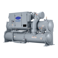
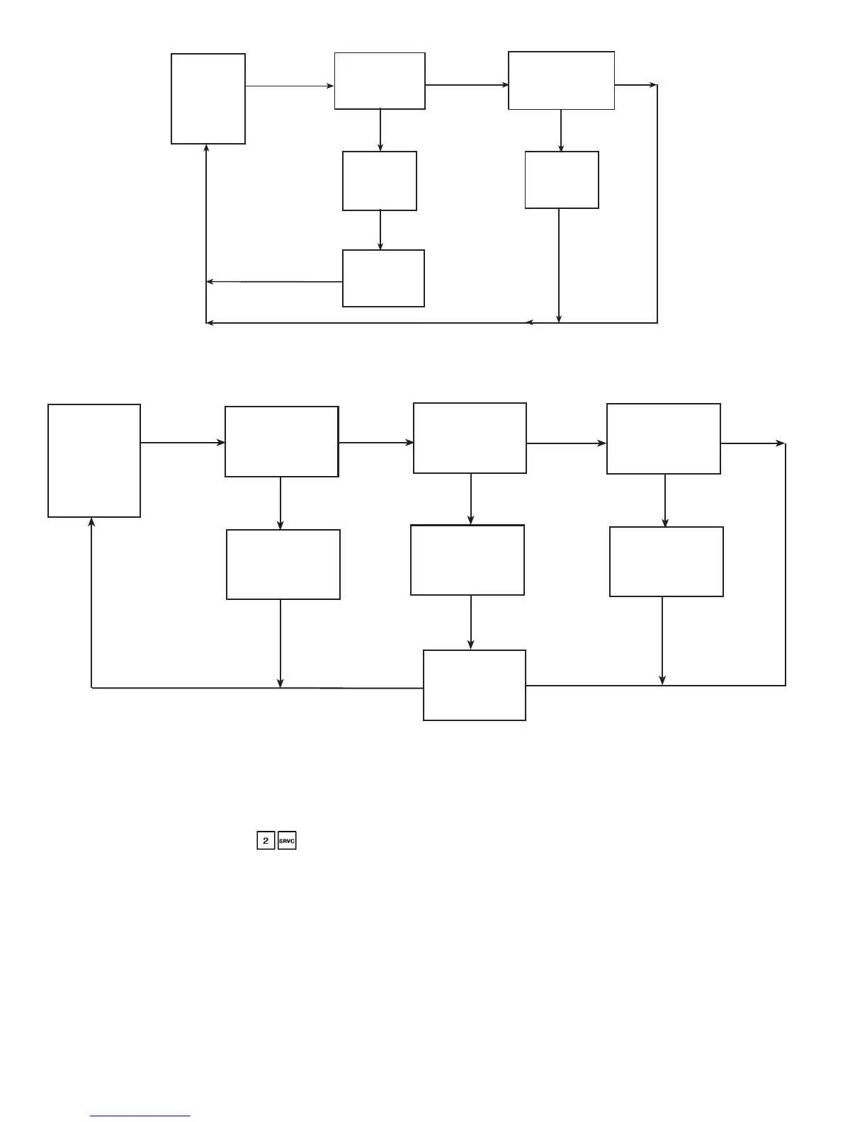
How to perform the actual start-up and understand the operating sequence.

FIELD WIRING DIAGRAMS

APPENDIX A - Compressor Must Trip Amps

APPENDIX B - Capacity Loading Sequence

APPENDIX C - Available Accessories

APPENDIX D - Compressor Protection Module Configuration

APPENDIX E - Pressure Drop Charts

APPENDIX E - Pressure Drop Charts (cont)

APPENDIX F - System Component Diagrams

APPENDIX F - System Component Diagrams (cont)

START-UP CHECKLIST

Preliminary Equipment Checks

Unit Start-Up Procedures

System Loop Pressure Drop Checks

PERFORM TEST FUNCTION

Configuration and Start-Up Data Recording

Final Start-Up Steps

Performing final valve/pump checks, starting the unit, and recording temperatures/pressures.

Related product manuals