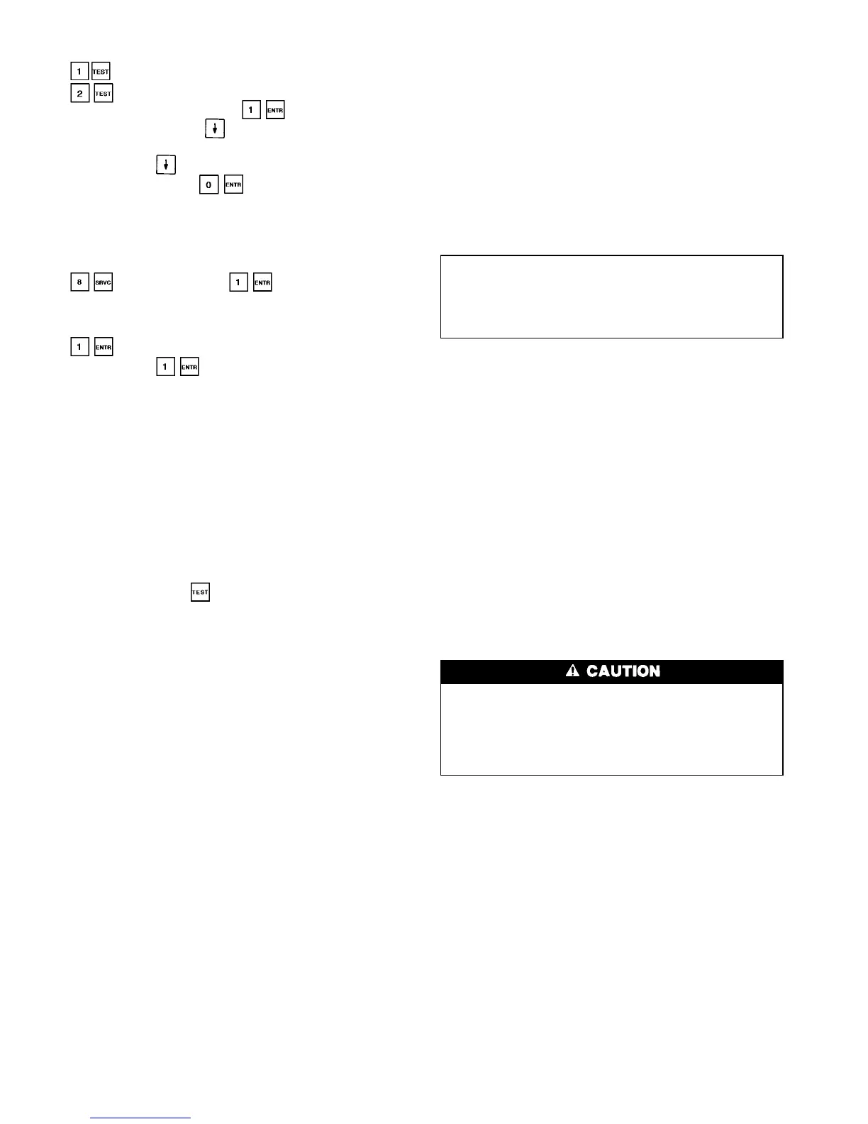
22. Restore main and control power to the machine. Using
the HSIO, enter the quick test function by pressing
(for compressor A1 or A2 replacement) or
(for compressor B1 replacement). Test the op-
eration of the solenoids. Press to test each loader
solenoid, then use the key to find the motor cool-
ing and oil solenoids and test them in the same manner.
Pressing the key after each output turns the
solenoid off (or press ). It is important that the
loaders are located properly (loader 1 on right hand side
when viewed from side opposite control box on 30HX
units, on left hand side when reaching over compressor
to far side on 30GX units).
23. Start the compressor using the Manual mode. Press
at the HSIO. Press to enable the Manual
mode. When display changes to ‘‘Enable,’’ switch the
Local-Off-Remote switch to the Local position. Select
the desired compressor using the down arrow key. Press
to start the compressor. Use the down arrow
key and press to energize both loaders. Let the
circuit stabilize with both loaders energized. Refer to the
Refrigerant and Oil Charging sections of this document
for recharging procedures and performance criteria.
BURNOUT CLEANUP PROCEDURE — If a screw com-
pressor motor burns out on a 30GX,HX chiller, a simple cleanup
should be performed. The following procedure provides the
minimum steps to be taken before restarting the circuit.
1. Remove the oil from the oil separator. This can be fa-
cilitated by connecting a hose to the port located on the
service valve entering the external oil filter. Run the hose
to a container(s) that can hold up to 5 to 6 gallons of oil.
To force out most of the oil in the separator pressurize
the circuit. To remove the remaining oil, the pre-lube
pump can be run in mode from the HSIO. To pre-
vent wear to the gears, do not allow the pre-lube pump
to operate ‘‘dry.’’
2. Remove the failed compressor following the Compres-
sor Changeout Sequence procedure above.
3. Once the compressor is removed access the oil catch pan
through the cooler-compressor mounting flange. Clean
out any debris which may have collected in the oil catch
pan.
4. Install a new compressor.
5. To dilute and remove any residual oil left in the sepa-
rator, pump approximately
1
⁄
2
gallon of compressor oil
into the oil separator using the Schrader port located on
top of the separator (30GX) or on the discharge line (30HX)
and remove using the pre-lube pump described in
Step 1.
6. Disconnect the hose from the external oil filter service
valve.
7. Install a new filter drier and compressor external oil
filter.
8. Measure in the amount of Castrol SW 220 Polyolester
oil as specified on the nameplate of the chiller.
9. Leak check, evacuate and recharge the machine as de-
scribed in this manual with the amount of R-134a stated
on the chiller nameplate.
10. Perform periodic acid checks on the circuit and change
the filter drier in the motor cooling line as necessary.
Use the Carrier Standard Service Techniques Manual as
a source of reference.
Moisture-Liquid Indicator — Clear flow of liquid
refrigerant indicates sufficient charge in the system. Note,
however, that bubbles in the sight glass do not necessarily
indicate insufficient charge. Moisture in the system
is measured in parts per million (ppm), changes of color of
indicator are:
Green — moisture is below 80 ppm;
Yellow-green (chartreuse) — 80 to 225 ppm (caution);
Yellow (wet) — above 225 ppm.
Change filter drier at the first sign of moisture in the
system.
IMPORTANT: Unit must in operation for at least
12 hours before moisture indicator can give an accu-
rate reading. With the unit running, the indicating el-
ement must be in contact with liquid refrigerant to give
true reading.
Filter Drier — Whenever moisture-liquid indicator shows
presence of moisture, replace filter drier. Refer to Carrier
Standards Service Technique Manual, Chapter 1, Refrig-
erants, for details on servicing filter driers.
Liquid Line Service Valve — This valve is located
ahead of the filter drier and provides a
1
⁄
4
-in. Schrader con-
nection (30GX only) for field charging. In combination with
compressor discharge service valve, each circuit can be pumped
down into the high side for servicing.
Thermistors — To aid in verifying thermistor perfor-
mance, resistances at various temperatures are listed for all
thermistors (except motor thermistors) in Tables 39Aand 39B.
See Table 40 for motor thermistor values.
LOCATION — General location of thermistor sensors and
terminal connections in the control box are listed in Table 2.
THERMISTOR REPLACEMENT
Liquid level thermistors are installed in the top of the
cooler using compression fittings. All other thermistors
are installed in wells and will slide out of the wells eas-
ily. The wells are under refrigerant pressure (cooler EWT
and LWT are under waterside pressure) and do not need
to be removed to replace a faulty thermistor.
To replace thermistors T1, T2, T5, or T6 (Entering,
Leaving Water; Discharge Gas Temperature):
Disconnect appropriate wires from PSIO-2 in unit control
box. Remove thermistor cable from harness. Remove and
discard original thermistor from well. Insert new thermistor
in well body to its full depth. Add a small amount of thermal
conductive grease to thermistor probe and well. Thermistors
are friction-fit thermistors and will slip back into well lo-
cated at the cooler head (T1, T2) or at the top of the con-
denser shell (T5, T6). Secure thermistor to well body with a
wire tie to prevent thermistor from working its way out of
the well. See Fig. 21.
To replace thermistors T3 or T4 (Liquid Level Sensors):
See the Inspecting/Opening Economizers section on
page 51 for information on transferring the refrigerant charge
58
 Loading...