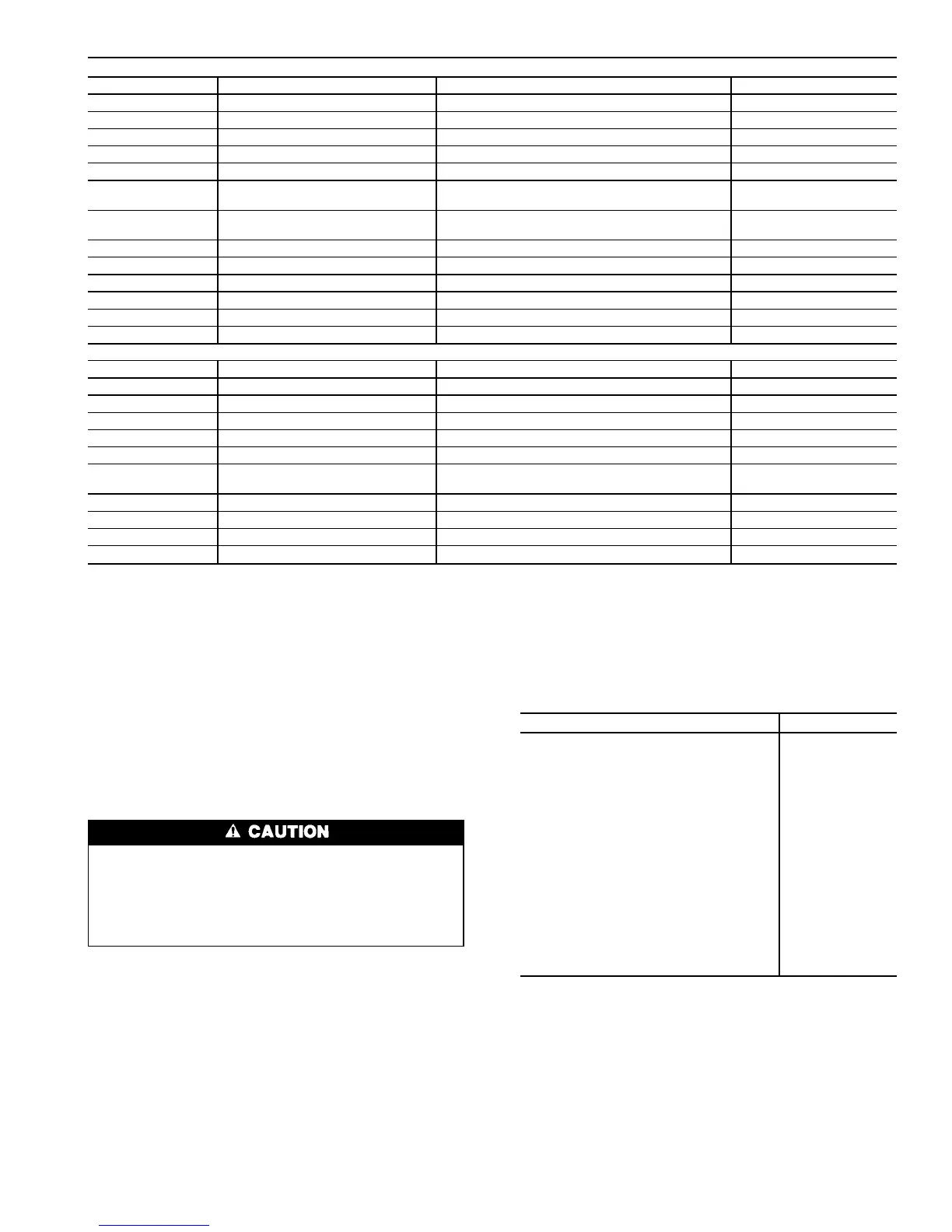
Table 2 — Thermistor and Transducer Locations
THERMISTORS
Sensor Description Location Connection Terminals
T1 Cooler Leaving Fluid Temp Cooler Head Leaving Fluid Side PSIO-2, J7 pins 2,3
T2 Cooler Entering Fluid Temp Cooler Head Entering Fluid Side PSIO-2, J7 pins 5,6
Motor Temp A1 Motor Temperature A1 Compressor A1 Junction Box CPM-A1, T terminals
Motor Temp A2* Motor Temperature A2 Compressor A2 Junction Box CPM-A2, T terminals
Motor Temp B1 Motor Temperature B1 Compressor B1 Junction Box CPM-B1, T terminals
T5 Discharge Gas Temp A Top of Condenser Circuit A (30HXC Only) PSIO-2, J7 pins 8,9
Top of Oil Separator Circuit A (All Other Units)
T6 Discharge Gas Temp B Top of Condenser Circuit B (30HXC Only) PSIO-2, J7 pins 11,12
Top of Oil Separator Circuit B (All Other Units)
LL-A (T3) Liquid Level Circuit A Top of Cooler Circuit A PSIO-1, J7 pins 5,6
LL-B (T4) Liquid Level Circuit B Top of Cooler Circuit B PSIO-1, J7 pins 8,9
T7 (optional)† Outdoor Air Thermistor Outside Air Stream PSIO-2, J7 pins 20,21
STP (optional)† Space Temperature Conditioned Space PSIO-2, J7 pins 23,24
T8 (optional)† Condenser Entering Water Temp Condenser Entering Fluid Line PSIO-2, J7 pins 14,15
T9 (optional)† Condenser Leaving Water Temp Condenser Leaving Fluid Line PSIO-2, J7 pins 17,18
PRESSURE TRANSDUCERS
Sensor Description Location Connection Terminals
DPT-A Discharge Pressure Circuit A Top of Condenser Circuit A (30HXC Only) PSIO-1, J7 pin 22
Top of Oil Separator Circuit A (All Other Units)
SPT-A Suction Pressure Circuit A Top of Cooler Circuit A PSIO-1, J7 pin 19
EPT-A Economizer Pressure Circuit A Economizer Line Entering Comp A PSIO-1, J7 pin 10
OPT-A1 Oil Pressure Compressor A1 Compressor A1 Oil Connection PSIO-1, J7 pin 25
OPT-A2* Oil Pressure Compressor A2 Compressor A2 Oil Connection PSIO-1, J7 Pin 1
DPT-B Discharge Pressure Circuit B Top of Condenser Circuit B (30HXC Only) PSIO-1, J7 pin 16
Top of Oil Separator Circuit B (All Other Units)
SPT-B Suction Pressure Circuit B Top of Cooler Circuit B PSIO-1, J7 pin 31
EPT-B Economizer Pressure Circuit B Economizer Line Entering Comp B PSIO-1, J7 pin 13
OPT-B Oil Pressure Compressor B Compressor B1 Oil Connection PSIO-1, J7 pin 28
*30HX206-271 only.
†Sensors are available as accessories for field installation.
The CPM communicates on the COMM3 communication
bus to the PSIO-1 module. Proper operation of the CPM board
can be verified by observing the 3 LEDs (light-emitting di-
odes) located on the board. The top LED is red and blinks
at a rate of once every 1 to 2 seconds. This indicates that the
module is powered and operating correctly. The middle LED
is yellow and blinks when there is an automatic reset alarm
condition. The yellow LED remains on and does not blink
for manual reset alarm conditions. The bottom LED is green
and blinks when the module is satisfactorily communicating
with the PSIO-1 module. The CPM communicates the status
of its inputs and outputs, and reports 18 different alarm con-
ditions to the PSIO-1. The alarms are listed in Table 3.
The CPM module has many features that are specifi-
cally designed to protect the compressor, including re-
verse rotation protection. Do not attempt to bypass or
alter any of the factory wiring. Any compressor opera-
tion in the reverse direction will result in a compressor
failure that will require compressor replacement.
The PSIO-1 will generate an alert when it receives an alarm
input from the CPM. The alert will be generated in a y.xx
format, where ‘‘y’’ refers to the compressor and ‘‘xx’’ to the
alarm value in Table 3 (decimal point removed). For ex-
ample, the HSIO might displayAlarm 1.70 for a voltage phase
reversal occurring on compressor A1. Similarly, the display
would read 5.85 for a motor overtemperature condition on
compressor B1.Alerts for compressorsA2 and B2 (if present)
would be generated as ‘‘2.xx’’and ‘‘6.xx,’’respectively. Alarm
codes 3 and 4 would not be used. Ending zeros are not
displayed.
The high-pressure switch is wired in series with the relay
coils of the 4 relays on the CPM. If this switch opens during
operation, all relays on the CPM are deenergized and the
compressor is stopped. The failure is reported to the PSIO-1
and the processor module locks off the compressor from re-
starting until the alarm is manually reset.
Table 3 — Compressor Protection Module
Feedback Codes
ALARM CONDITION VALUE
High Pressure Switch Trip 1.0
No Motor Current 2.0
Current Imbalance Alarm 10% 2.5
Current Imbalance Warning 10% 2.7
Current Imbalance 18% 3.0
Single Phase Current Loss 3.5
High Motor Current 4.0
Ground Fault 5.0
Voltage Imbalance Alarm 3% 5.5
Voltage Imbalance Warning 3% 5.7
Voltage Imbalance 7% 6.0
Voltage Phase Reversal 7.0
Contactor Failure 7.5
Current Phase Reversal 8.0
Motor Overtemperature 8.5
Open Thermistor 9.0
Configuration Header Fault 9.5
Shorted Thermistor 10.0
No Error 0
Wye-Delta vs Across-the-line (XL) Starting
Option —
All 30GX,HX chillers operating at voltages of
208/230-3-60 or 230-3-50 (5 or 8 at Position 12 in model
number) are supplied with factory installed Wye-Delta start-
ers. All other voltage options can be ordered with either
Wye-Delta or XL starting options. The XL starting method
is the most cost effective and simply starts the compressor
motor in a Delta configuration (the motors are designed for
continuous operation in this configuration) using a single con-
tactor. See Fig. 2. This is the simplest starting method to use
and is ideal where starting current does not require limiting.
5
 Loading...