Table 40 — Thermistor Temperatures vs
Resistance, Motor Temperature Thermistors
TEMP
(F)
TEMP
(C)
RESISTANCE
(Ohms)
−22 −30 88,480.0
−13 −25 65,205.0
−4 −20 48,536.0
5 −15 36,476.0
14 −10 27,663.0
23 −5 21,163.0
32 0 16,325.0
41 5 12,696.0
50 10 9,949.5
59 15 7,855.5
68 20 6,246.0
77 25 5,000.0
86 30 4,028.4
95 35 3,265.7
104 40 2,663.2
113 45 2,184.2
122 50 1,801.2
131 55 1,493.1
140 60 1,243.9
149 65 1,041.4
158 70 875.8
167 75 739.7
176 80 627.6
185 85 534.9
194 90 457.7
203 95 393.3
212 100 339.3
221 105 293.8
230 110 255.3
239 115 222.6
248 120 194.8
NOTE: Motor temperature thermistor values must be verified using
resistance. Voltage drop cannot be used.
Table 41 — Thermistor Depth
UNIT MODEL
NUMBER
THERMISTOR DEPTH
‘‘X’’-in. (mm)
30GX080-090 6.00 (152.4)
30GX105-115 4.25 (108.0)
30GX125-136 5.56 (141.2)
30GX150,151 6.00 (152.4)
30GX160,161 4.25 (108.0)
30GX175,176 4.25 (108.0)
30GX205-226 3.94 (100.0)
30GX250-265 4.82 (122.4)
30HXA,C076-086 5.13 (130.3)
30HXA,C096 6.00 (152.4)
30HXA,C106 4.25 (108.0)
30HXA,C116-126 5.13 (130.3)
30HXA,C136-146 6.00 (152.4)
30HXA,C161-171 4.25 (108.0)
30HXA,C186 5.56 (141.2)
30HXA,C206 3.94 (100.0)
30HXA,C246-271 4.82 (122.4)
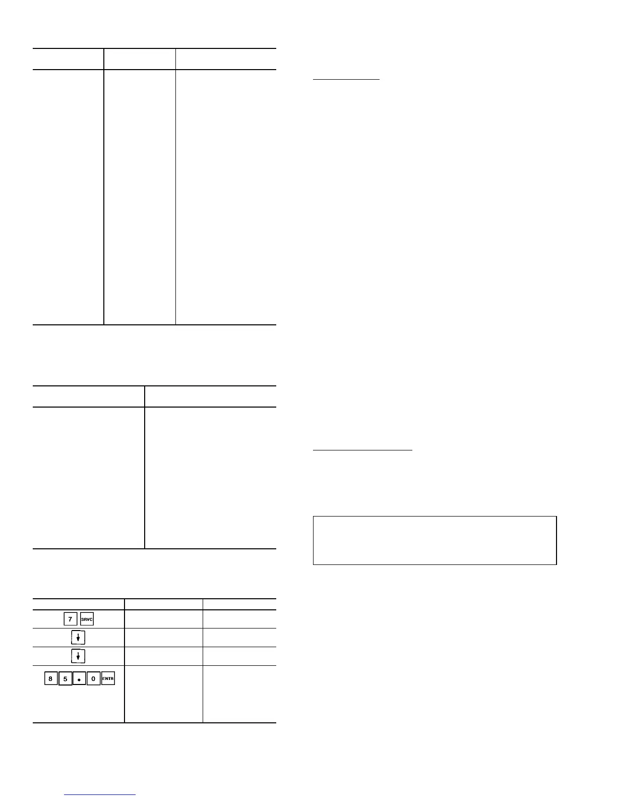
Table 42 — Calibrating Pressure Transducers
(Pressure Gage Installed)
KEYPAD ENTRY DISPLAY RESPONSE COMMENTS
CALIBRATION
OFFSET
CIRCUIT A
PRESSURE
Discharge Pressure
84.2 PSI
Current reading is
displayed.
Discharge Pressure
85.0 PSI
Enter gage pressure
reading to nearest
tenth. Control will
allow offset of up to
6 psig. Transducer
calibration is now
complete.
Safety Devices — The 30GX/HX chillers contain many
safety devices and protection logic built into the electronic
control. Following is a description of the major safeties.
COMPRESSOR PROTECTION
Motor Overload — One factory preset solid-state overload
protects each compressor against overcurrent. Do not by-
pass the overload or make any changes to the overload
setting. Determine the cause for trouble and correct the prob-
lem before resetting a tripped overload. In addition to the
overload, each compressor is further protected by the
Compressor Protection Module. Each module has a factory
installed and configured 8-pin header. The configuration of
this header defines the must-trip amps at which the CPM
will turn the compressor off. See Appendix D for correct set-
ting of overload and configuration headers.
Each CPM board also reads the status of each compres-
sor’s high-pressure switch. All compressors have factory-
installed high-pressure switches. For 30GX units, the switch
is set to trip at 303 ± 7 psig (2089 ± 48 kPa). The setting
for 30HXA units is 275 ± 7 psig (1896 ± 48 kPa) and for
30HXC units the setting is 191 ± 7 psig (1317 ± 48 kPa).
If the switch opens during operation, the compressor will be
shut down. The CPM will reset automatically when the
switch closes, however, a manual reset is required to restart
the compressor.
OIL SEPARATOR HEATERS (30GX) — Each oil separator
circuit has a heater mounted on the underside of the vessel.
The heater is energized with control circuit power. After a
prolonged shutdown or service job, additional time may be
required before starting the unit. Oil heaters are energized
when the discharge gas temperature falls below 105 F
(40.6 C). The heaters are deenergized when the discharge
gas temperature rises above 110 F (43.3 C). The control will
allow the chiller to attempt to start with the heaters ener-
gized and will keep the heaters on, even when running, until
the discharge gas temperature reaches 110 F (43.3 C). Note
that the oil heaters are deenergized if the oil level switch is
open.
COOLER PROTECTION
Low Water Temperature — Microprocessor is programmed
to shut the chiller down if the leaving fluid temperature drops
below 34 F (1.1 C) for water or more than 8° F (4.4° C)
below set point for brine units. When the fluid temperature
rises 6° F (3.3° C) above the leaving fluid set point, the safety
resets and the chiller restarts. Reset is automatic as long as
this is the first occurrence of the day.
IMPORTANT: If the unit is installed in an area where
ambient temperatures fall below 32 F (0° C), inhibited
ethylene glycol or other suitable solution must be used
in the chilled fluid circuit.
Relief Devices — Fusible plugs are located in each cir-
cuit (30GX only) between the condenser and the liquid line
shutoff valve.
PRESSURE RELIEF VALVES — Valves are installed in each
circuit and are located on all coolers. One relief valve is also
installed on each 30HXC condenser. Both circuits’ oil sepa-
rators on 30GX and 30HXA units have factory-installed
relief valves as well. These valves are designed to relieve if
an abnormal pressure condition arises. Relief valves on all
coolers and 30HXC condensers relieve at 220 psi (1517 kPa).
Relief valves on 30GX and 30HXA oil separators relieve at
320 psi (2206 kPa). Units with factory-installed suction serv-
ice valves also have a relief valve in each compressor dis-
charge line. These valves are designed to relieve at 350 psig
(2413 kPa). These valves should not be capped. If a valve
relieves, it should be replaced. If the valve is not replaced,
it may relieve at a lower pressure, or leak due to trapped dirt
from the system which may prevent resealing.
62
 Loading...