1-1 T -309
SECTION 1
INTRODUCTION
1.1 INTRODUCTION
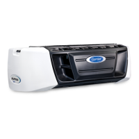
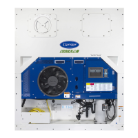
The C arrier Transicold model 69NT20--531-300 units
are of lightweight aluminum frame construction,
designedtofitinthefrontofacontainerandserveasthe
container front wall.
They are one piece, self-contained, all electric units
which are fitted with cooling and heating systems to
provide precise temperature control.
The units are supplied with a complete charge of
refrigerant R-134a and compressor lubricating oil and
are ready for operation upon installation. Forklift
pockets are provided for unit installation and removal.
The base unit operates on nominal 380/460 volt, 3
phase, 50/60 hertz power. An optional autotransformer
maybefittedtoallowoperationonnominal190/230,3
phase,50/60 hertzpower. Power for the control system
is provided by a transformer which steps t he supply
power down to 18 and 24 volts, single phase.
The controller is a Carrier Transicold Micro-Link 2i
microprocessor. The controller will operate
automatically to select cooling, holding or heating as
required t o maintain the desired set point temperature
within very close limits.
The controller is fitted with a keypad and display for
viewingorchanging operatingparameters. Thedisplay
isalsoequippedwithlightstoindicatevariousmodesof
operation.
1.2 CONFIGURATION IDENTIFICATION
Unit identification information is provided on a model
plate located to the left of the economizer. The plate
provides the unit model number and the unit parts
identification number (PID). The model number
identifies the overall unit configuration while the PID
provides information on specific optional equipment,
factory provision to allow for field installation of
optional equipment and differences in detailed parts.
Configuration i dentification for the models covered
herein areprovided in the Carrier Transicold Container
Unit Matrixmanual,publicationT--300. Printedcopies
oftheT --300 maybe obtained from Carrier Transicold.
Also,aweeklyupdatedcopymaybefoundattheCarrier
Web site, www.carrier.refrigeration.com.
1.3 OPTION DESCRIPTIONS
Variousoptionsmaybefactoryorfieldfittedtot hebase
unit. B rief descriptions of the options are provided in
the following subparagraphs.
1.3.1 Battery
The controller may be fitted with standard replaceable
batteries or a rechargeable battery pack.
1.3.2 Dehumidification
The unit m ay be fitted with a humidity sensor. This
sensor allows setting of a humidity set point in the
controller. In the dehumidification mode thecontroller
willoperatetoreduce internalcontainer moisturelevel.
1.3.3 Control Box
The control box is constructed of composite material
and may be fitted with a lockable door.
1.3.4 Temperature Readout
The unit may be fitted with suction and discharge
temperature sensors. The sensor readings may be
viewed on the controller display.
1.3.5 Pressure Readout
Theunitmaybefittedwithfactoryinstalledsuctionand
discharge pressure gauges. The unit is fitted with
suctionanddischargetransducers.Thereadingsmaybe
viewed on the controller display.
1.3.6 Interrogator
UnitsthatusetheDataCORDERfunctionarefittedwith
interrogator receptacles for connection ofequipment to
download the recorded data. Two receptacles may be
fitted, one accessible from the front of the unit and the
other mounted inside the container (with the USDA
receptacles).
1.3.7 Remote Monitoring
The unit may be fitted with a remote monitoring
receptacle. This item allows connection of remote
indicators for COOL, DEFROST and IN RANGE.
1.3.8 Communications
Theunitmaybefittedwitha communicationsinterface
module. The communications interface module is a
slave module which allows communication with a
master central monitoring station. The module will
respondto communicationandreturninformationover
the main power line. Refer to the ship master system
technical manual for further information.
1.3.9 Compressor
The unit is fitted with a scroll compressor.
1.3.10 Back Panels
Backpaneldesignsthat may be fittedinclude panels of
aluminumandstainlesssteel. Panelsmaybefittedwith
access doors and/or hinge mounting.

 Loading...