6-16T -309
5. Press the ENTER key on the keypad.
6. TheDisplaywillshowthemessage“ProSoFt.”This
message will last for up to one minute.
7. The Displaymodule will read “Pro donE” whenthe
software loading has loaded. (If a problem occurs
while loading the software: the Display will blink
the message “Pro FAIL” or “bad 12V”. Turn start-
stop switch OFF and remove the card.)
8. Turn unit OFF, via start-stop switch (ST).
9. Remove the programming card from the program-
ming/softwareportandreturntheunitto normalop-
eration by placing the start-stop switch in the ON
position.
b. Procedure for loading Configuration Software
1. Turn unit OFF using start-stop switch (ST).
2. Insert the programming card, for Configuration
Software,into theprogramming/softwareport. (See
Figure 6-18.)
3. Turn unit ON using start-stop switch (ST).
4. The Display module will show “nt40” on the l eft
LCD display and “531###” on the right LCD dis-
play.“###”willindicatet hedashnumberforagiven
unit modelnumber, usethe UPor DOWNARROW
key to scroll through the list to obtain the proper
model dash number. For example, to program a
model number 69NT40-531-05, press the UP or
DOWN ARROW key until the right display shows
“nt40” on the right display and “53105” on the left.
(If a defective card is being used, the Display will
blink the message “bAd CArd”. Turn start-stop
switch OFF and remove the card.)
5. Press the ENTER key on the keypad.
6. When the software loading has successfully com-
pleted, the Display will show the message “EEPrM
donE.” (If a problem occurs while loading the soft-
ware,theDisplaywillblinkthemessage“ProFAIL”
or “bad 12V.” Turn start-stop switch OFF and
remove the card.)
7. Turn unit OFF using start-stop switch (ST).
8. Remove the programming card from the program-
ming/softwareportandreturntheunitto normalop-
eration by placing the start-stop switch in the ON
position.
6.21.4 Removing and Installing a Module
a. Removal:
1. Disconnect all front wire harness connectors and
move wiring out of way.
2 The lowercontrollermounting is slotted, loosenthe
topmountingscrew(seeFigure 6-18)andliftupand
out.
3 Disconnectthebackconnectorsandremovemodule.
4 W hen removing the replacement module from its
packaging,notehowitispackaged.Whenreturning
theold module forservice, placeit in thepackaging
in thesamemanner as thereplacement. Thepackag-
ing has been designed to protect the module from
both physical and electrostatic discharge damage
during storage and transit.
b.Installation:
Install the module by reversing the removal steps.
Torque values for mounting screws (item 2, see
Figure 6-18) are 0.23 mkg (20 inch-pounds). Torque
value for the connectors is 0.12 mkg (10 inch-pounds).
6.22 TEMPERATURE SENSOR SERVICE
Procedures for service of the Return Recorder, Return
Temperature, S upply Recorder, Supply Temperature,
Ambient, Defrost Temperature, Compressor Discharge
and Compressor Suction temperature sensors are
provided in the following sub paragraphs.
6.22.1 Sensor Checkout Procedure
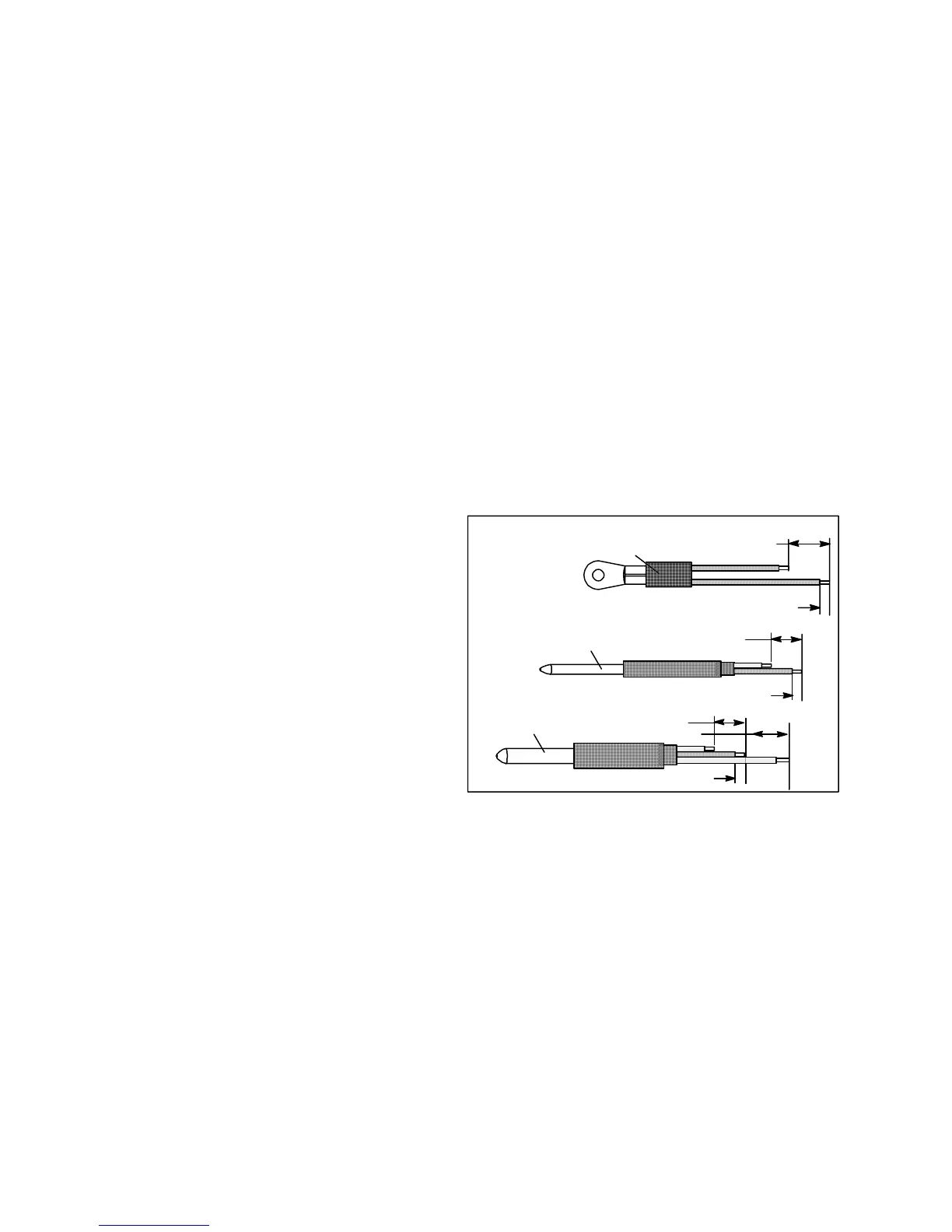
Sensor
40 mm (1 1/2 inch)
6.3 mm (1/4 inch)
Mounting Stud Type
Sensor
40 mm (1-1/2 inches)
6.3 mm (1/4 inch)
Bulb Type
Dual Sensor
40 mm (1-1/2 inches)
6.3 mm (1/4 inch)
Figure 6-19 Sensor Types
To check a sensor reading, do the following:
a. Removethesensorandplaceina0_C(32_F)ice-wa-
ter bath. The ice-water bath i s prepared by filling an
insulated container (of sufficient size to completely
immersebulb)withicecubesorchippedice,thenfill-
ing voids between ice with water and agitating until
mixture reaches 0_C(32_F) measured on a labora-
tory thermometer.
b. Start unit and check sensor reading on the control
panel.Thereadingshouldbe0_C(32_F).Iftheread-
ing is correct, reinstall sensor; if it is not, continue
with the following.
c. Turn unit OFF and disconnect power supply.
d. Refertoparagraph6.21andremovecontrollertogain
access to the sensor plugs.

 Loading...