6-15
T -309
12
3
4
5
2
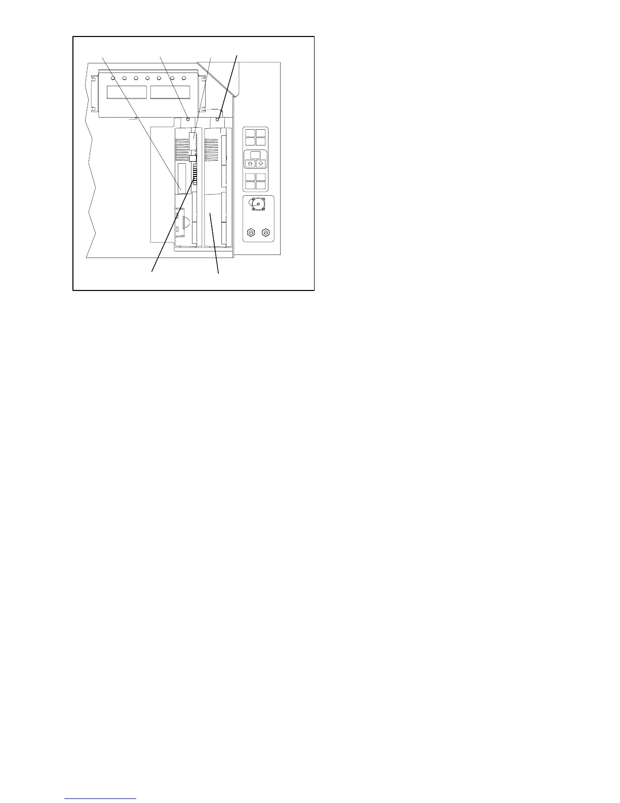
1. Controller Software
Programming Port
2. Mounting Screw
3. Controller
4. Expansion Module
5. Test Points
Figure 6-18 Controlle r Sec tion of the Control Box
a. Obtain a grounding wrist strap (Carrier Transicold
part number 07--00 --304--00)and a static dissipation
mat (Carrier Transicold part number 07--00304 --00.
The wrist strap, when properly grounded, will dissi-
pate any potential buildup on the body. The dissipa-
tion mat will provide a static-free work surface on
which to place and/or service the modules.
b. Disconnect and secure power to the unit.
c. Placestrap on wrist andattachthe ground end t o any
exposed unpainted m etal area on the refrigeration
unit frame (bolts, screws, etc.).
d. Carefullyremovethemodule.Donottouchanyofthe
electrical connections if possible. Place the module
on the static mat.
e. Thestrapshouldbewornduringanyserviceworkon
a module, even when it is placed on the mat.
6.21.2 Controller Trouble-Shooting
Agroupoftestpoints(TP,seeF igure 6-18)areprovided
on the controllerfortrouble-shooting electricalcircuits
(seeschematicdiagram,section7). Adescriptionofthe
test points follows:
NOTE
Use a digital voltmeter to measure ac voltage
between TP’s and ground (TP9), except for
TP8.
TP1
Thistestpointenablest heusertocheckifthecontroller
unloader solenoid valve relay (TU) is open or closed.
TP2
This test point enables the user to check if the high
pressure switch (HPS) is open or closed.
TP3
This test point enables the user to check if the water
pressure switch (WP) contact is open or closed.
TP 4
This test point enables the user to check if the internal
protectorforthecondenserfanmotor(IP-CM)isopenor
closed.
TP 5
This test point enables the user to check if the internal
protectors for the evaporator fan motors (IP-EM1 or
IP-EM2) are open or closed.
TP 6
This test point is not used in this application.
TP 7
Thistestpointenablest heusertocheckifthecontroller
economizersolenoid valve relay(TS) is open orclosed
TP 8
This test point enables the user to check power to the
suction modulator valve.
TP 9
This test point is the chassis (unit frame) ground
connection.
TP 10
This test point enables the user to check if the heat
terminationthermostat(HTT)contactisopenorclosed.
6.21.3 Controller Programming Procedure
Toloadnewsoftwareintothemodule,theprogramming
card is i nserted into the programming/software port.
CAUTION
The unit mustbe OFFwhenever aprogram-
ming card is inserted or removed from the
controller programming port.
NOTE
Themetal dooron the programming cardmust
be facing to the left when inserting.
a. Procedure for loading Operational Software
1. Turn unit OFF, via start-stop switch (ST).
2. Insert the programming card for Operational Soft-
ware into the programming/software port. (See
Figure 6-18)
3. Turn unit ON, via start-stop switch (ST).
4. The Display module will alternate back and forth
between the messages “rEV XXXX” and “Press
EntR”. (If a defective card is beingused theDisplay
willblink the message“bAd CArd”. Turnstart-stop
switch OFF and remove the card.)

 Loading...