Send document comments to nexus7k-docfeedback@cisco.com
8-10
Cisco Nexus 7000 Series NX-OS Interfaces Configuration Guide, Release 5.x
OL-23435-03
Chapter 8 Configuring IP Tunnels
Verifying the IP Tunnel Configuration
The following example shows how to add a tunnel interface to the VRF:
switch# configure terminal
switch(config)# interface tunnel 0
switch(config-if)# vrf member RemoteOfficeVRF
switch(config-if)# ip address 209.0.2.1/16
switch(config-if)# copy running-config startup-config
Verifying the IP Tunnel Configuration
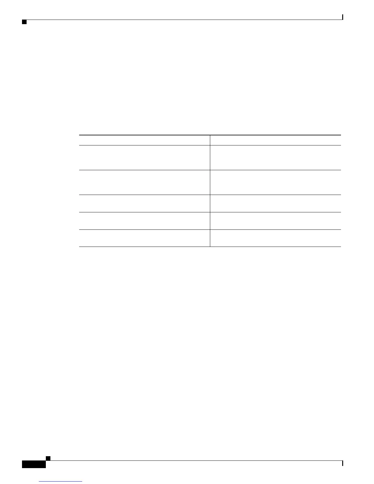
To verify IP tunnel configuration information, perform one of the following tasks:
Configuration Examples for IP Tunneling
The following example shows a simple GRE tunnel. Ethernet 1/2 is the tunnel source for router A and
the tunnel destination for router B. Ethernet interface 2/1 is the tunnel source for router B and the tunnel
destination for router A.
router A:
feature tunnel
interface tunnel 0
ip address 209.165.20.2/8
tunnel source ethernet 1/2
tunnel destination 192.0.2.2
tunnel mode gre ip
tunnel path-mtu-discovery 25 1500
interface ethernet1/2
ip address 192.0.2.55/8
router B:
feature tunnel
interface tunnel 0
ip address 209.165.20.1/8
tunnel source ethernet2/1
tunnel destination 192.0.2.55
tunnel mode gre ip
interface ethernet 2/1
ip address 192.0.2.2/8
Command Purpose
show interface tunnel number Displays the configuration for the tunnel interface
(MTU, protocol, transport, and VRF). Displays
input and output packets, bytes, and packet rates.
show interface tunnel number brief Displays the operational status, IP address,
encapsulation type, and MTU of the tunnel
interface.
show interface tunnel number description Displays the configured description of the tunnel
interface.
show interface tunnel number status Displays the operational status of the tunnel
interface.
show interface tunnel number status
err-disabled
Displays the error disabled status of the tunnel
interface.

 Loading...