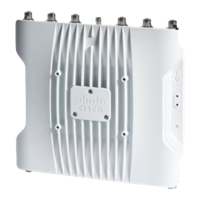
Figure 22: Position of the Ground Pad on the Right Side of the AP
Ground pad, where the ground strap screw holes are located.1
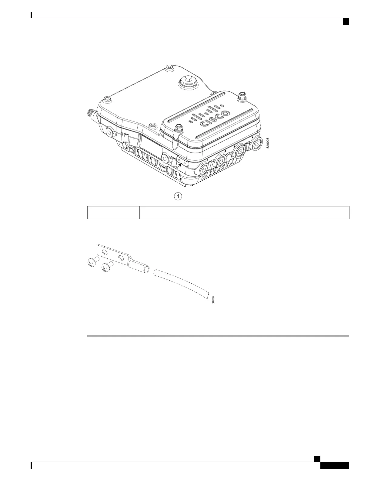
Step 4 Connect the grounding lug to the access point grounding screw holes using the supplied two Phillips head
screws (M4 x10 mm) with lock washers. Tighten the grounding screw to 22 to 24 lb-in (2.49 to 2.71 Nm).
Step 5 If necessary, strip the other end of the ground wire and connect it to a reliable earth ground, such as a grounding
rod or an appropriate grounding point on a metal streetlight pole that is grounded.
Using the Reset Button
The access point has a reset button located on the right side of the unit (see the following figure).
Cisco Catalyst IW6300 Heavy Duty Series Access Point Hardware Installation Guide
39
Installing the Access Point
Using the Reset Button

 Loading...