EasyManuals Logo
Home>Cisco>Network Hardware>GS7000

Cisco GS7000 User Manual

Cisco GS7000
254 pages
To Next Page IconTo Next Page
To Previous Page IconTo Previous Page
Page #118 background imageLoading...
Page #118 background image
Chapter 4 Setup and Operation
98
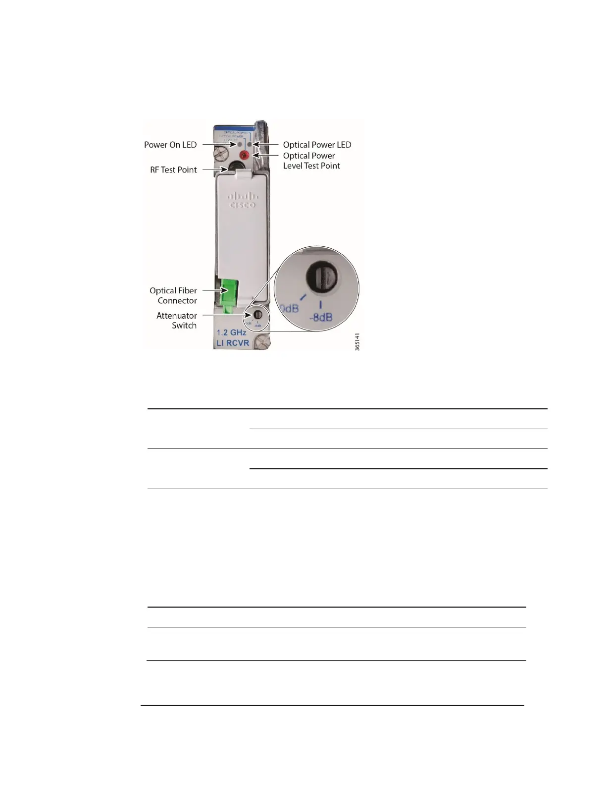
6 Set the receiver module attenuator switch as follows:
IF received optical power is...
THEN set the attenuator
switch to...
Standard Receiver
2 to +2 dBm
-8 dB
-6 to -2 dBm
0 dB
Low Input Receiver
-6 to -2 dBm
-8 dB
-10 to -6 dBm
0 dB
7 For standard input receiver, check the RF level at the -20 dB RF test point on each
forward path receiver. Signal level should be +7 dBmV at the test point with 0
dBm optical input power and 2.5% index modulation of the laser headend
transmitter. (With optical receiver attenuator set to the -8 dB switch setting.) This
represents an optical receiver output of +27 dBmV. For low input receiver follow
the same process to check the RF level and refer the table below.
For standard receiver
For low input receiver
Att/OMI
Output level
27dBmV
27dBmV
8 dB/2.5%
Input optical
power
0dBm
-4dBm
8 dB/2.5%
8 The next step depends on your RF output levels.
IF your RF output ports will...
and you have...
THEN...

Table of Contents

Other manuals for Cisco GS7000

Questions and Answers:

Question and Answer IconNeed help?

Do you have a question about the Cisco GS7000 and is the answer not in the manual?

Cisco GS7000 Specifications

General IconGeneral
BrandCisco
ModelGS7000
CategoryNetwork Hardware
LanguageEnglish

Related product manuals