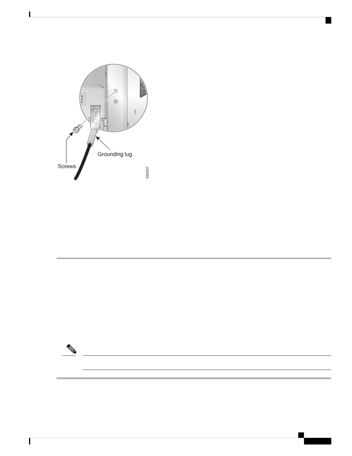
Figure 41: Grounding Lug— Cisco NCS 5504
Step 3 Use the Phillips screwdriver to carefully tighten the screws until the grounding lug is held firmly to the chassis. Do not
overtighten the screws.
Step 4 Use the wire stripper to strip one end of the 6-AWG wire approximately 0.75 inches (19.05 mm).
Step 5 Insert the 6-AWG wire into the wire receptacle on the grounding lug.
Step 6 Use the crimping tool to carefully crimp the wire receptacle around the wire; this step is required to ensure a proper
mechanical connection.
Step 7 Connect the opposite end of the grounding wire to the appropriate grounding point at your site to ensure an adequate
chassis ground.
What to do next
Continue to start up the router.
Connect AC Power Supply to AC Power Source
Before you begin
See Weight, Quantity and Power Consumption, on page 10 to ascertain the power needs for the router.
Take care when connecting units to the supply circuit so that wiring is not overloaded.
Note
Step 1 For each 3-kW Standard AC power supply, connect an AC power cable to the AC power source and to the power receptacle
on the power supply.
Hardware Installation Guide for Cisco NCS 5500 Series Modular Routers
73
Install the Chassis
Connect AC Power Supply to AC Power Source
 Loading...