• No parity
Step 2 Connect an RJ-45 rollover cable to the CONSOLE SERIAL PORT.
You can find this cable in the accessory kit.
Step 3 Route the RJ-45 rollover cable through the center slot in the cable management system and then to the console or modem.
Step 4 Connect the other end of the RJ-45 rollover cable to the console or to a modem.
If the console or modem cannot use an RJ-45 connection, use the DB-9F/RJ-45F PC terminal adapter found in the
accessory kit for the router. Alternatively, you can use an RJ-45/DSUB F/F or RJ-45/DSUB R/P adapter, but you must
provide those adapters.
What to do next
You are ready to create the initial router configuration (see Create the Initial Router Configuration, on page
93).
Connect the Management Interface
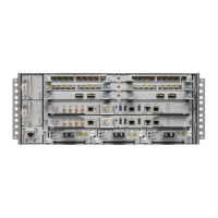
The Route Processor management port (MGMT ETH) provides out-of-band management, which enables you
to use the command-line interface (CLI) to manage the router by its IP address. This port uses a 10/100/1000
Ethernet connection with an RJ-45 interface.
In a dual Route Processor router, you can ensure that the active Route Processor card is always connected to
the network by connecting the management interface on both Route Processor cards to the network. That is,
you can perform this task for each Route Processor card. When the Route Processor card is active, the router
automatically has a management interface that is running and accessible from the network.
Note
To prevent an IP address conflict, do not connect the MGMT 10/100/1000 Ethernet port until the initial
configuration is complete. For more information, see Create the Initial Router Configuration, on page 93.
Caution
Before you begin
You must have completed the initial router configuration (see Create the Initial Router Configuration, on page
93).
Step 1 Connect a modular, RJ-45, UTP cable to the MGMT ETH port on the Route Processor card.
Step 2 Route the cable through the central slot in the cable management system.
Step 3 Connect the other end of the cable to a 10/100/1000 Ethernet port on a network device.
Hardware Installation Guide for Cisco NCS 5500 Series Modular Routers
81
Connect Router to the Network
Connect the Management Interface

 Loading...
