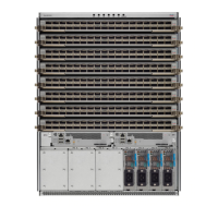
Figure 52: Aligning a CFP2 Module into a Port Socket
Step 3 Slide the CPT2 module in until the EMI gasket flange makes contact with the line card faceplate.
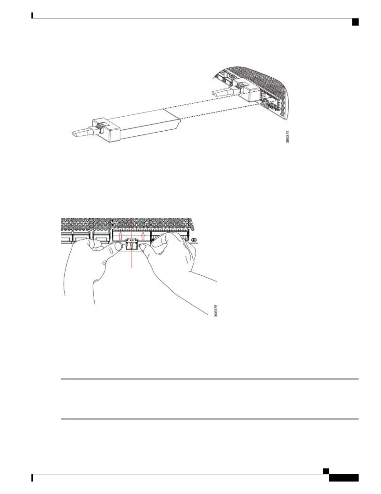
Step 4 Press firmly on the front of the CFP2 module with your thumbs to fully seat it in the transceiver socket.
The CFP2 module is properly seated in the slot by applying symmetrical force of at least 80N on its front surface, along
the centerline. The latching mechanisms on both the sides of the pluggable should be fully engaged, and the electrical
connectors should be completely mated.
Figure 53: Installing a CFP2 Module into a Port Socket
Step 5 When you are ready to attach the network cable interface, remove the dust plugs and inspect and clean fiber connector
end faces, and then immediately attach the network interface cable connectors into the CFP2 module optical bores.
Online insertion and removal (OIR): When you insert a CFP2 module that is configured for 150Gbps (8 QAM),
there will be a delay in the laser-on process for both optics controllers due to flapping. This laser-on process
can take up to 120 seconds to complete.
Note
Removing a CFP2 Module
To remove a CFP2 module, follow these steps:
Step 1 Attach an ESD-preventive wrist or ankle strap and follow its instructions for use.
Hardware Installation Guide for Cisco NCS 5500 Series Modular Routers
91
Connect Router to the Network
Removing a CFP2 Module
 Loading...