2-2
Cisco PIX Security Appliance Hardware Installation Guide
78-15170-03
Chapter 2 PIX 501
PIX 501 Product Overview
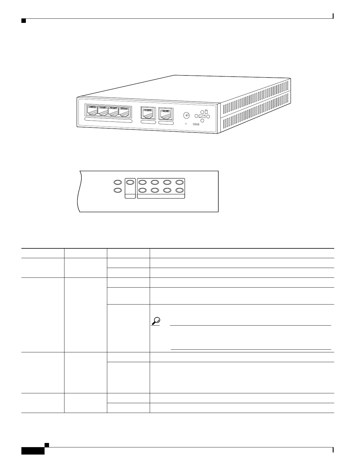
Figure 2-2 shows the rear view of the PIX 501.
Figure 2-2 PIX 501 Rear Panel
Figure 2-3 shows the PIX 501 front panel LEDs.
Figure 2-3 PIX 501 Front Panel LEDs
Table 2-1 lists the states of the PIX 501 front panel LEDs.
67849
POWER
4
3
2
1
0
CONSOLE
3.3V 4.5A
POWER
VPN TUNNEL
LINK/ACT
100 MBPS
12
3
4
61926
Table 2-1 PIX 501 Front Panel LEDs
LED Color State Description
POWER Green On The device is powered on.
Off The device is powered off.
LINK/ACT Green Flashing Network activity, such as Internet access, is present.
On The correct cable is in use, and the connected equipment has power and
is operational.
Off No link is established.
Tip If the LINK/ACT LED does not light up, you might be using the
wrong type of cable. Try replacing the yellow, straight-through
Ethernet cable with the orange, crossover Ethernet cable.
VPN TUNNEL Green On One or more IKE/IPSec VPN tunnels are established.
Off One or more IKE/IPSec VPN tunnels are disabled. If the standard
configuration is not modified to support VPN tunnels, the LED does not
light up because it is disabled by default. Also, the LED does not light up
when PPTP/L2TP tunnels are established.
100 MBPS Green On The interface is enabled at 100 Mbps (autonegotiated).
Off The interface is enabled at 10 Mbps.

 Loading...


