2-3
Cisco PIX Security Appliance Hardware Installation Guide
78-15170-03
Chapter 2 PIX 501
Installing the PIX 501
Installing the PIX 501
Place the PIX 501 on a flat, stable surface. The PIX 501 is not rack mountable.
To install the PIX 501, perform the following steps:
Step 1 Connect Port 0, the outside Ethernet port, to the public network.
• Use the yellow Ethernet cable (72-1482-01) to connect the device to a switch or hub.
• Use the orange Ethernet cable (72-3515-01) to connect the device to a DSL modem, cable modem,
or router.
Step 2 Connect your PC or the other network devices to one of the four switched inside ports (numbered 1
through 4).
Connecting a Power Supply Module to the PIX 501
This section describes how to connect the power supply module to a PIX 501. Use this information in
conjunction with the Regulatory Compliance and Safety Information document.
To connect the power supply module to the PIX 501, perform the following steps:
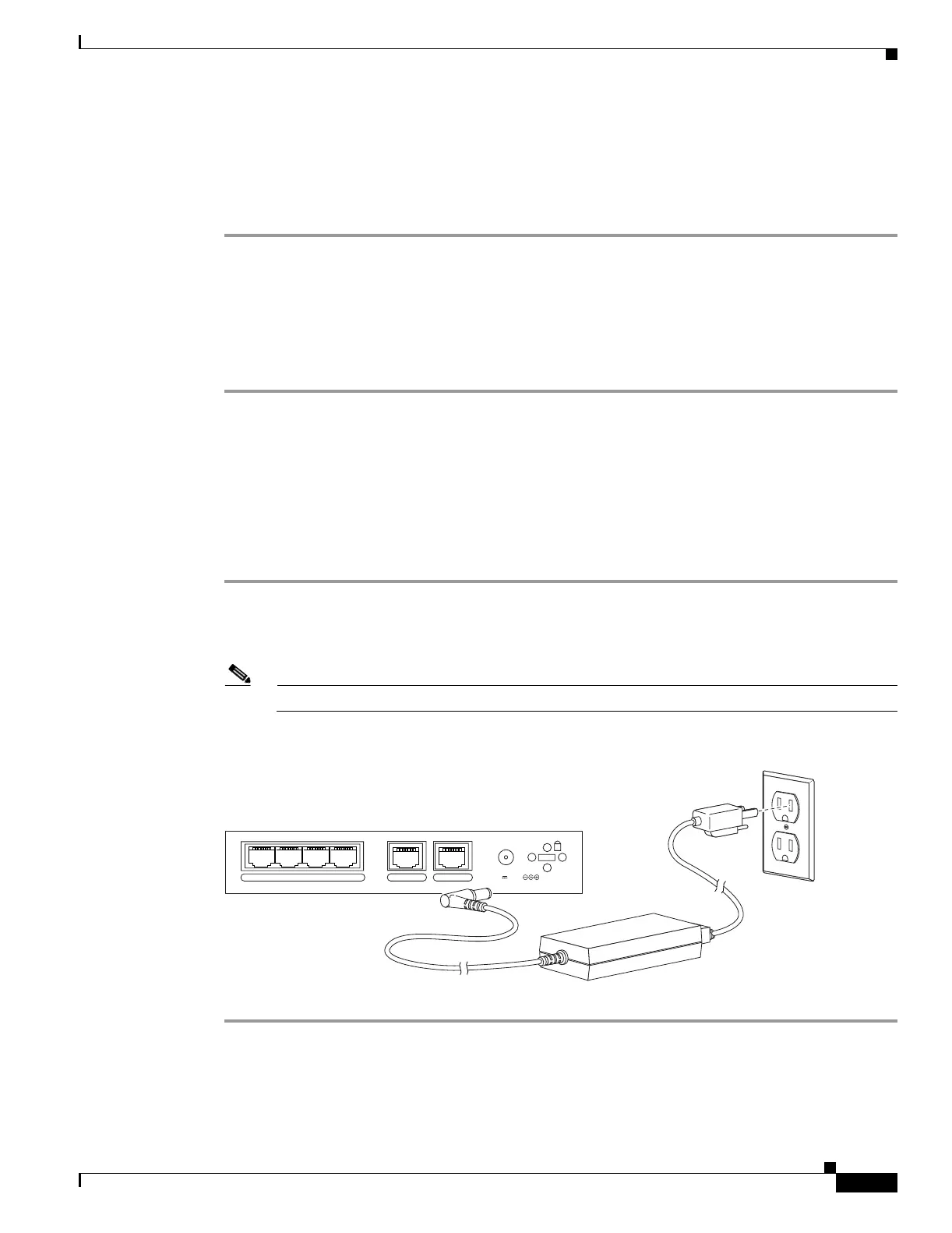
Step 1 Connect the small, round connector of the power supply cable to the power connector on the rear panel
(see Figure 2-4).
Step 2 Connect the AC power connector of the power supply input cable to an electrical outlet.
Note The PIX 501 does not have a power switch. Completing Step 2 powers on the device.
Figure 2-4 Connecting the Power Supply Module to the PIX 501
POWER
43
2
1
0 CONSOLE
3.3V 4.5A
71534
Power supply

 Loading...


