Communication Guide, ©ComAp – March 2014 51
IGS-NT Communication Guide 03-2014.pdf
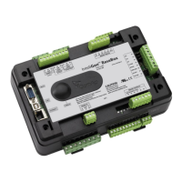
I-LB+ hardware setup
(all jumpers in those positions)
According HW or SW control of modem
Selection of CAN address. Open = ADDR1, Close = ADDR2
It is possible to use up to two I-LB+ devices in modem mode on CAN(2)
bus. Let jumper open in case of using one I-LB+ module. Other I-LB
module has to have this jumper closed. (read more about I-LB+ module)
Set jumper to RS232 position
Open = terminator not connected, Close = terminator connected
Open = terminator not connected, Close = terminator connected
Equipment
I-LB+ unit, Analog, ISDN or GSM modem
Analog, ISDN or GSM modem
Active Call
Function
When active calls are activated for alarms on site (warning, shut-down…) the controller calls to the
preselected telephone number and sends the ANT archive file.
Software (e.g. InteliMonitor) on the PC side must be running and waiting for active call.
Controllers
Hint:
Active call uses for communication the modem connection.
Equipment
The same as for modem connection
Controller setup
(Setpoints/Comms settings group)
Act. calls/SMS: AcallCH1(-3)-Type = DATA
Act. calls/SMS: AcallCH1(-3)-Addr = telephone number

 Loading...


