Communication Guide, ©ComAp – March 2014 70
IGS-NT Communication Guide 03-2014.pdf
Connection of I-LB, combination of different CAN bus speeds:
This connection allows PC communication to all controllers in the system (e.g. via InteliMonitor),
including a distant InteliMains unit.
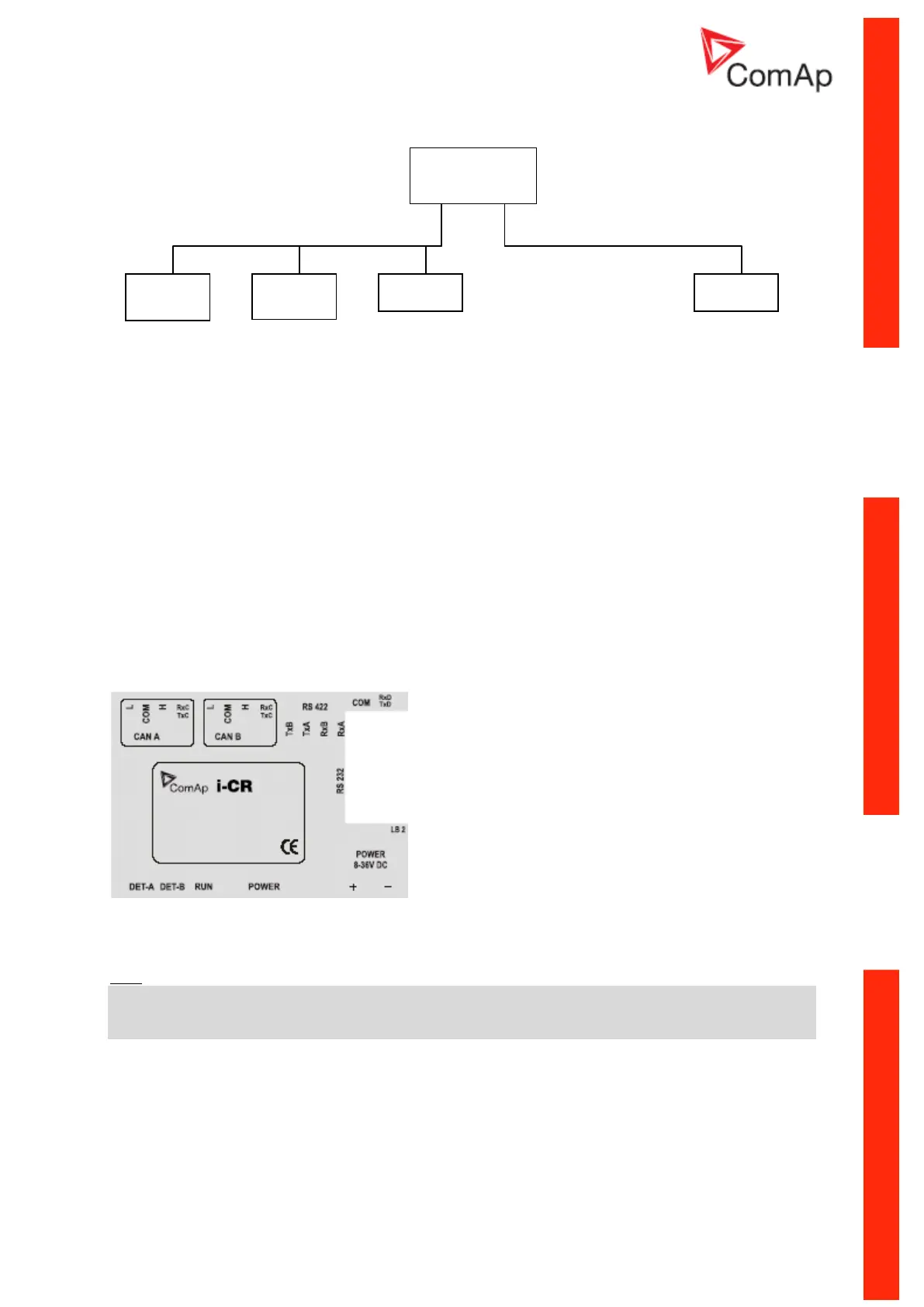
I-CR module functions:
- Intercontroller CAN bus extension (one or more I-CR modules can be used).
- Intercontroller CAN bus bus-tie bridging – makes groups of controllers in segments A and B
“invisible” one for another depending on bus-tie breaker state, keeping the PC communication (I-
LB, IG-IB) in function for all controllers.
- Peripheral CAN bus extension
I-CR configuration jumpers:
P2 – Forces 250 kbps mode (32C) on CAN A, otherwise speed autodetection is used.
P3 – Forces 250 kbps mode (32C) on CAN B, otherwise speed autodetection is used.
P4 – Activates Filter mode (bus-tie bridging).
P5 – Forces alternate controller address 3 for bus-tie status reading (default controller address is 4).
P10 – If “H” network configuration used (two I-CR units), it must be switched to RS-422 mode.
I-CR indication and diagnostic LEDs:
For more detailed information about I-CR, see the Application sheet “Extending the CAN bus” or
IGS-NT-x.y-Installation guide.pdf.
Hint:
CAN bus has to be terminated at both ends.
In the case of surge hazard (connection out of building in case of storm etc.) see the “Recommended
CAN/RS485 connection” chapter of the IGS-NT-2.4-Installation guide.pdf.
total segment length up to 900 m
total segment length up to 200 m

 Loading...


