Communication Guide, ©ComAp – March 2014 73
IGS-NT Communication Guide 03-2014.pdf
I-CR-R module functions:
- Intercontroller CAN bus redundancy – basic description of terminology used:
o Local CAN bus – a bus going from the module to the local controller(s) = within one
switchboard; name on the sticker CAN1 CONTROLLER; in standard installation (with no
redundancy) this would be the intercontroller bus (CAN2)
o Primary intercontroller CAN bus – a bus interconnecting all I-CR-R modules and
providing 1 to 1 replacement of standard intercontroller CAN bus (CAN2); name on the
sticker CAN EMS
o Backup intercontroller RS485 bus – secondary bus interconnecting all I-CR-R modules;
transmits only intercontroller communication (Load Sharing, VAr Sharing, Power
Management), not the remote communication (I-LB, IG-IB connection to a PC monitoring
tool)
- The module preferably uses the Primary CAN bus line for data transfer. However, if the
connection from any of the controllers connected to other I-CR-R modules is broken the module
automatically re-routes it to the Backup RS485 line and continues in operation. From controllers’
point of view, no data transfer interruption is observed.
- It is possible to indicate the problem with Primary or Backup buses using “fake” SHBOUT6
message which is normally used for signal sharing among the controllers. See jumper description
further in the text.
- Intercontroller CAN bus extension – each I-CR-R module provides also CAN bus extension in the
same way as I-CR module, i.e. creates segments of the bus where the length of the line is limited
within the segment only, not within the whole system.
Note 1: The redundancy system only makes sense if the cables of Primary and Backup buses are
placed physically into different cable routes! Placing them into the same cable route increases the risk
of damage of both cables at once.
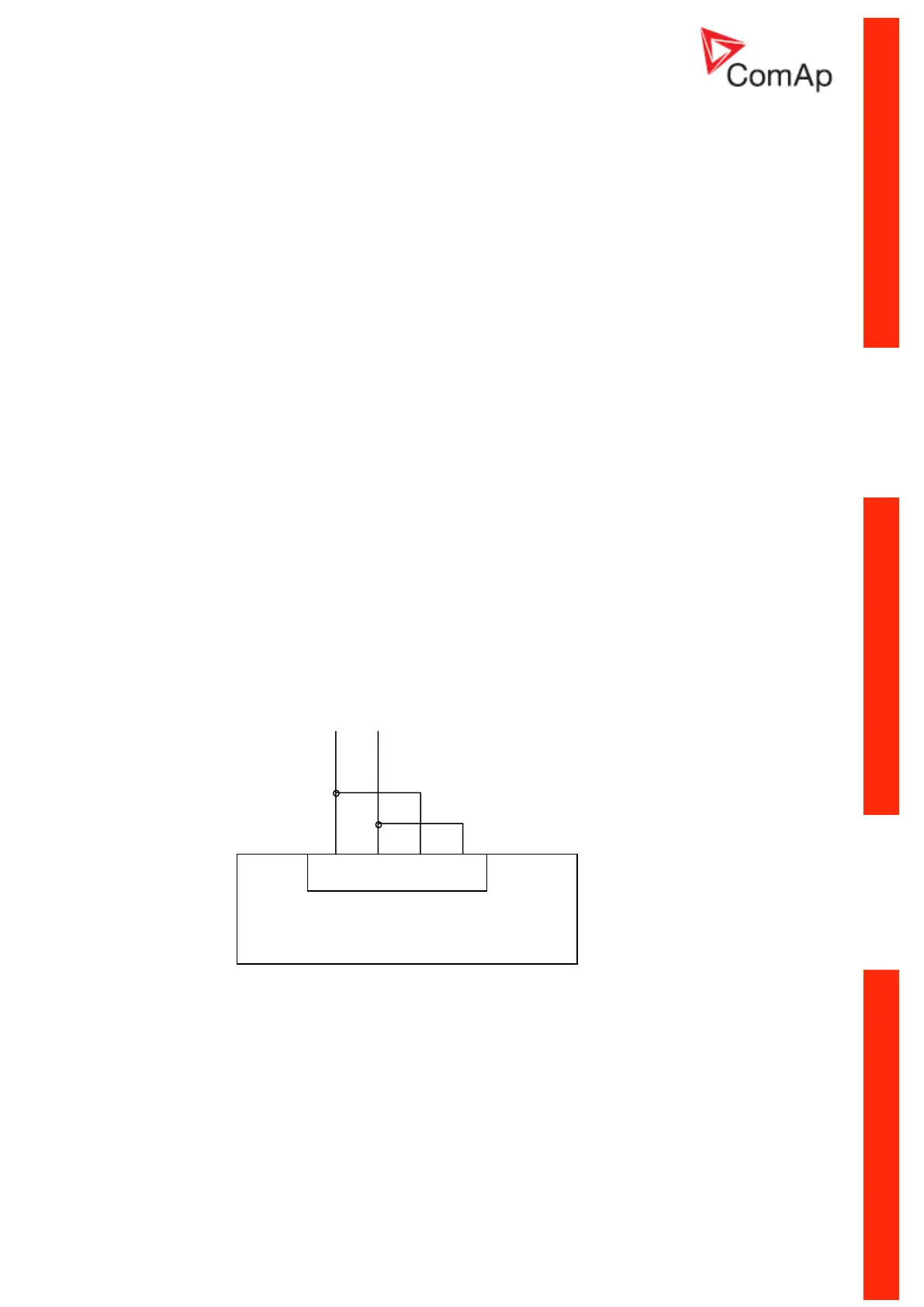
Note 2: For proper connection of RS485 line, connect the terminals TxA and RxA together and
terminals TxB and RxB together. This should be done on each I-CR-R module and with short wire
(see drawing).
I-CR-R configuration jumpers:
P3 – Forces 8C (50 kbps) mode on Primary intercontroller bus (name at the original sticker CAN
EMS); if not active, 32C (250 kbps) mode is automatically used.
Note: All I-CR-R modules within the system must be switched to the same mode, otherwise the
primary intercontroller CAN bus won’t work.
P4 – Enables transmission of SHBOUT6 message to local CAN bus; the message is intended to
transmit indication and error flags from the module to the controllers to make the status of the module
RS485 line going to other I-CR-R modules

 Loading...


