Communication Guide, ©ComAp – March 2014 83
IGS-NT Communication Guide 03-2014.pdf
Availability of embaded galavanic separation of RS485 port in ComAp products
All IGS-NT controllers - port RS485(1)
All IGS-NT controllers - port RS485(2)
IG-Display, IS-Display - port RS485
InteliVision 8 - port RS485, CAN
InteliVision 5 - port RS485
InteliVision 5 RD - port RS485
InteliVision 5 CAN - port CAN
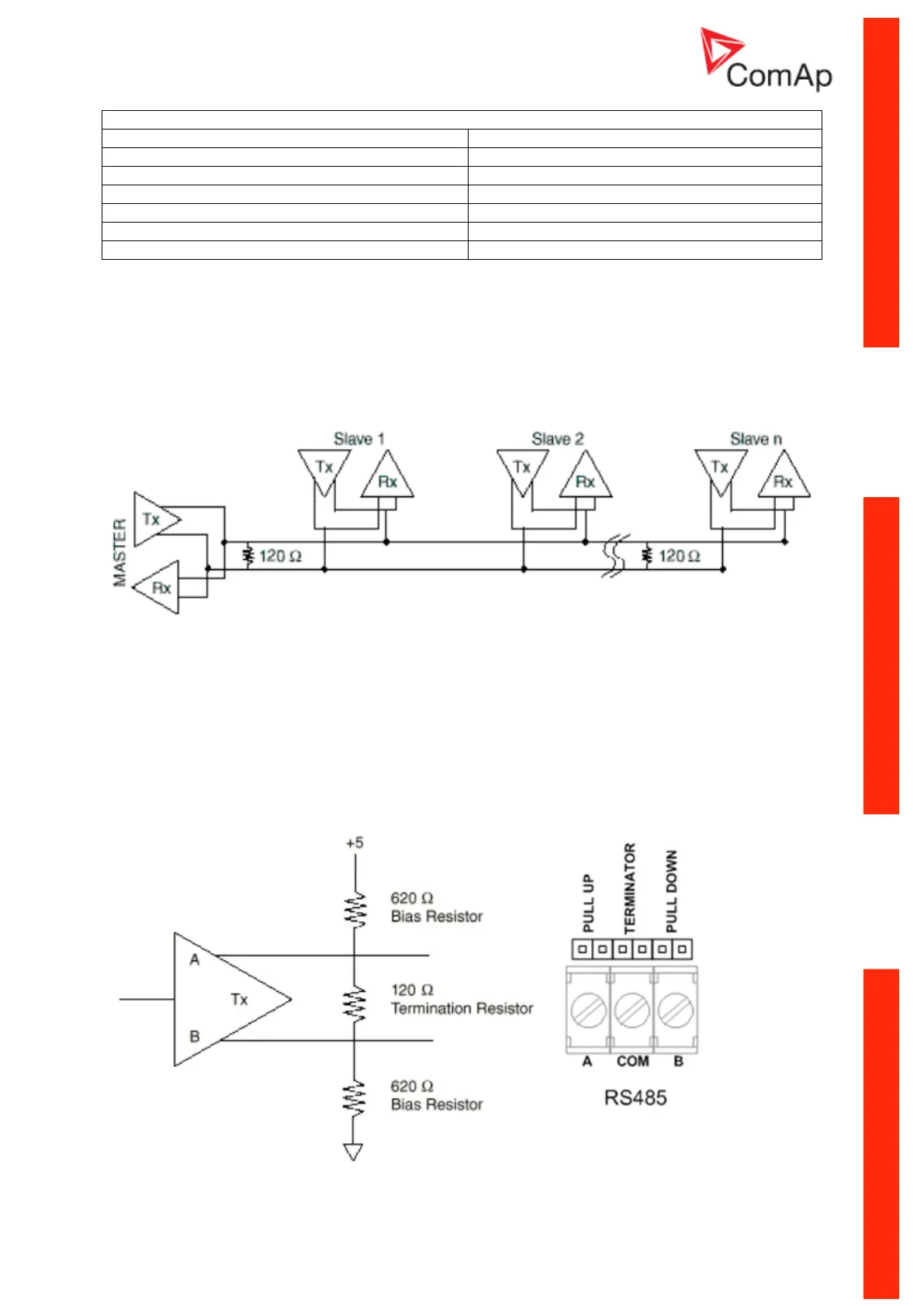
Termination Resistors:
Because each differential pair of wires is a transmission line, you must properly terminate the line to
prevent reflections. A common method of terminating a two-wire multidrop RS-485 network is to install
terminating resistors at each end of the multidrop network. If you daisy-chained multiple instruments
together, you need a terminating resistor at only the first and last instruments. The terminating resistor
should match the characteristic impedance of the transmission line (typically 100–120 Ohms).
Bias Resistors:
The transmission line into the RS-485 port enters an indeterminate state when it is not being
transmitted to. This indeterminate state can cause the receivers to receive invalid data bits from the
noise picked up on the cable. To prevent these data bits, you should force the transmission line into a
known state. By installing two 620 Ohm bias resistors at one node on the transmission line, you can
create a voltage divider that forces the voltage between the differential pair to be less than 200 milli-
Volts, the threshold for the receiver. You should install these resistors on only one node. The figure
below shows a transmission line using bias resistors. Bias resistors are placed directly on the PCB of
controller. Use jumpers PULL UP / PULL DOWN to connect the bias resistors.

 Loading...


