assembly
15. Carefully uncoil the blade holding it at arms length.
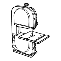
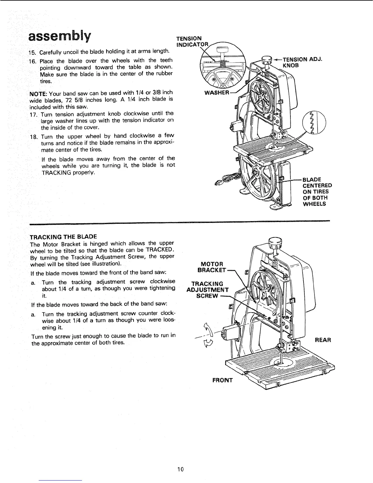
!6, Place the blade over the wheels with the teeth
pointing downward toward the table as shown.
Make sure the blade is in the center of the rubber
tires.
NOTE: Your band saw can be used with 1/4 or 3/8 inch
wide blades, 72 5/8 inches long. A 1/4 inch blade is
included with this saw.
17. Turn tension adjustment knob clockwise until the
large washer lines up with the tension indicator on
the inside of the cover.
18. Turn the upper wheel by hand clockwise a few
turns and notice if the blade re mains in the approxi-
mate center of the tires.
If the blade moves away from the center of the
wheels while you are turning it, the blade is not
TRACKING properly.
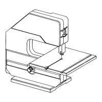
TENSION
INDICAT__ _
WASHERJ
DE
CENTERED
ON TIRES
OFBOTH
WHEELS
TRACKING THE BLADE
The Motor Bracket is hinged which allows the upper
wheel to be tilted so that the blade can be TRACKED.
By turning the Tracking Adjustment Screw, the upper
wheel will be tilted (see iliustration).
if the blade moves toward the front of the band saw:
a. Turn the tracking adjustment screw clockwise
about 1/4 of a turn, as though you were tightening
it.
If the blade moves toward the back of the band saw:
a. Turn the tracking adjustment screw counter clock-
wise about 114 of a turn as though you were loos-
ening it.
Turn the screw just enough to cause the blade to run in
the approximate center of both tires.
MOTOR
TRACKING
ADJUSTMENT
SCREW ---,,
REAR
FRONT
10
 Loading...