assembly
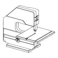
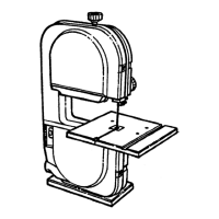
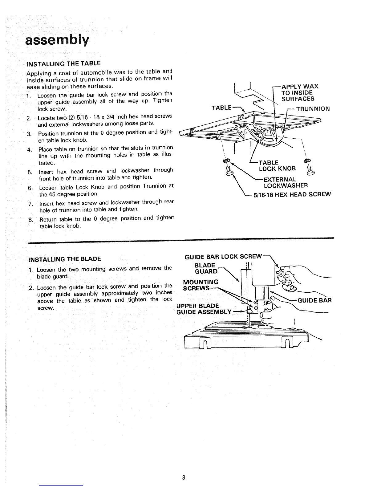
INSTALLING THE TABLE
Applying a coat of automobile wax to the table and
inside surfaces of trunnion that slide on frame will
ease sliding on these surfaces.
1. Loosen the guide bar lock screw and position the
upper guide assembly all of the way up. Tighten
lock screw.
2. Locate two (2) 5/16 - 18 x 3/4 inch hex head screws
and external Ioc kwashers among loose parts.
3. Position trunnion at the 0 degree position and tight-
en table lock knob.
4. Place table on trunnion so that the slots in trunnion
line up with the mounting holes in table as illus-
trated.
5. Insert hex head screw and Iockwasher through
front hole of trunnion )nto table and tig hten.
6. Loosen table Lock Knob and position Trunnion at
the 45 degree position.
7. Insert hex head screw and Iockwasher through rear
hole of trunnion into table and tighten.
8. Return table to the 0 degree position and tighten
table lock knob.
| _ --APPLY WAX
TO NSaDE
____,_ _ SURFACES
TABLE _F_ _ F-'TRUNN'ON
\
_ --TABLE _'_
__ LOCK KNOB
_--- EXTERNAL
___ LOCKWASH ER
5/16-18 HEX HEAD SCREW
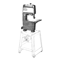
INSTALLING THE BLADE GUIDE BAR LOCK SCREW_
1. Loosen the two mounting screws and remove the BLADE --, t11 1_-7--'--'_
blade guard. MOUNTING
2. Loosen the guide bar lock screw and position the SCREWS_ ! } I 11!1_ _J_
upper guide assembly approximately two inches _----_LI l_lltl_----__._ _
__ __'_ GUIDE BAR
abOVescrew,the table as shown and tighten the Iock UPPER B L/_p,.Eo,._,____-_ Z_._
GUIDE ASSEMBLY -"-_ _[;Z_- ._,':"_-'_
 Loading...