assembly
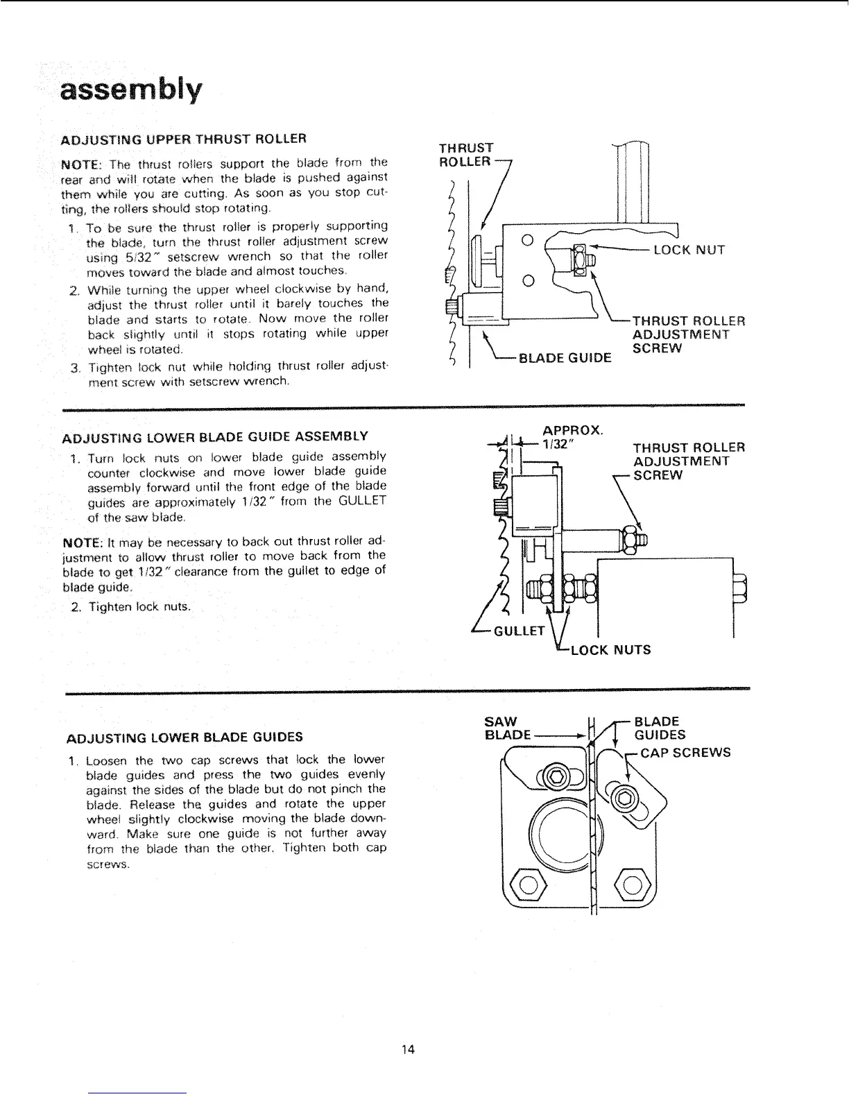
ADJUSTING UPPER THRUST ROLLER
NOTE: The thrust toilers support the b}ade from the
rear and w_ll rotate when the blade is pushed against
them wh_le you are cutting. As soon as you stop cut-
ting, the rotters should stop rOtating,
t To be sure the thrust roller is properly supporting
the blade, turn the thrust roller adjustment screw
using 5/32" setscrew wrench so that the roller
moves towar(_ the blade and almost touches.
2, Whiie turn_ng th_ upper wheel clockwise by hand,
adjust the thrust roller until it barely touches the
blade and starts to rotate. Now move the roller
back shghtly until it stops rotating while upper
wheel is rotated.
3. T_gn[er,. lock nut while holding thrust roller adjust,
ment screw with setscrew wrench.
THRUST
ROLLER --7
/
/
/
}°
0
_--- BLADE
ADJUSTING LOWER BLADE GUIDE ASSEMBLY
1. Turn Iock nuts on lower blade guide assembly
counter clockw=se and move lower blade guide
assembly forward until the front edge of the blade
guides are app{oximately 1/32" from the GULLET
of the _w bfade,
NOTE: It may be necessary to back out thrust roller ad-
lustment to allow thrust roller to move back from the
blade to get !132" clearance from the gullet to edge of
blade guide.
2. Tighten lock nuts,
GUIDE
LOCK NUT
rHRUST ROLLER
ADJUSTMENT
SCREW
APPROX.
_ 1t32" THRUST ROLLER
Z _ "2_ ADJUSTMENT
°i
ADJUSTING LOWER BLADE GUIDES
1. Loosen the two cap screws that lock the lower
blade guides and press the two guides evenly
against the s_des of the blade but do not pinch the
blade. Release the guides and rotate the upper
wheet stightty clockwise moving the blade down-
ward. Make sure one guide is not further away
from the blade than the other, Tighten both cap
SCre_¢S.
SAW _ _4"-" B LAD E
BLADE " I_ _ GUIDES
" CAP SCREWS
14
 Loading...