1
Introduction
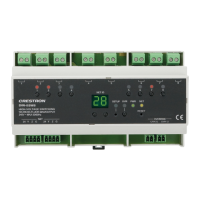
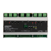
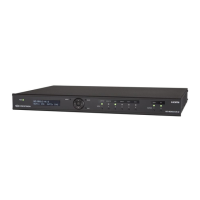
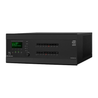
The Crestron® DM-MD8X8-CPU3, DM-MD16X16-CPU3, DM-MD32X32-CPU3, and related
redundant power supply models (DM-MD8X8-CPU3-RPS, DM-MD16X16-CPU3-RPS, and
DM-MD32X32-CPU3-RPS) are designed to accommodate DMC Series input and output
cards (sold separately):
• The DM-MD8X8-CPU3(-RPS) provides 8 input card slots and 4 dual output card
slots.
• The DM-MD16X16-CPU3(-RPS) provides 16 input card slots and 8 dual output
card slots.
• The DM-MD32X32-CPU3(-RPS) provides 32 input card slots and 16 dual output
card slots.
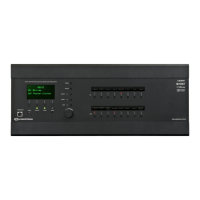
The switchers also accommodate the included DMC-CPU3 card, which is based on the
3-Series® platform. The RPS switchers also include redundant power supplies to ensure
continuous reliable operation for mission-critical applications.
This guide provides information about the following:
• Physical Description
• Using the Web Interface
• Using the Front Panel LCD
• Using the Routing Push Buttons
In addition, information about DMC Series cards is provided in the appendix of this
manual.
For additional information about the switchers, visit the DM-MD8X8-CPU3,
DM-MD16X16-CPU3, DM-MD32X32-CPU3, DM-MD8X8-CPU3-RPS, DM-MD16X16-CPU3-
RPS, and DM-MD32X32-CPU3-RPS product pages on the Crestron website
(www.crestron.com).
 Loading...