5 Configuration D-Link Web Smart Switch User Manual
The default community strings for the Switch used for SNMP v.1 management access are:
Read_Only: The community with read-only privilege allows authorized management stations to retrieve MIB
objects. The default name is public.
Read_Write: The community with read/write privilege allows authorized management stations to retrieve and
modify MIB objects. The default name is private.
Trap Setting: Traps are messages that alert network personnel of events that occur on the Switch. Such
events can be as severe as a reboot (someone accidentally turned the Switch OFF), or less serious events
such as a port status change. The Switch can generate traps and send them to the trap recipient (i.e.
network administrator).
Setting up a Trap: Select Enable, enter a Trap Name, add the IP of the device to be monitored, and select
the event(s) to trap. The available trap Events to choose from include:
SNMP Authentication Traps
System Device Bootup
Fiber Link Up / Link Down
Twisted Pair Link Up / Link Down
RSTP Port State Change
Firmware Upgrade State
Trap notification if POE Power On / Off
Trap notification if POE Power Error
Trap notification if over max power budget
Note: Trap Name must be selected from a
Community Name
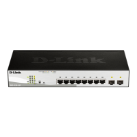
System > Password Access Control
Setting a password is a critical tool for managers to secure the Web-Smart Switch. After entering the old
password and the new password twice, click Apply for the changes to take effect.
Figure 45 – System > Password Access Control
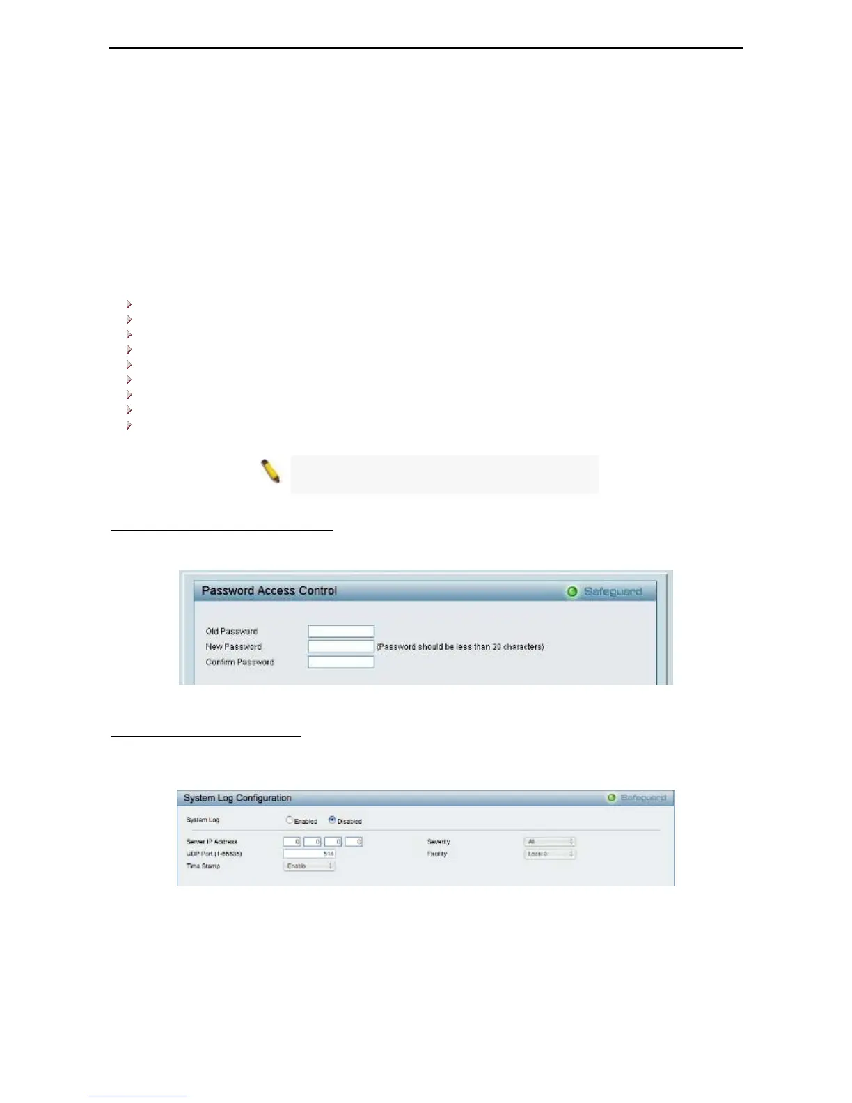
System > System Log Settings
System Logs record and manage events, as well as report errors and informational messages. Message
severity determines a set of event messages that will be sent. Click Enable so you can start to configure the
related settings of the remote system log server, then press Apply for the changes to take effect.
Figure 46 – System > System Log Settings
Server IP Address: Specifies the IP address of the system log server.
UDP Port: Specifies the UDP port to which the server logs are sent. The possible range is 1 – 65535, and
the default value is 514.
Time Stamp: Select Enable to time stamp log messages.
2
2
9
9
 Loading...