DGS-1510 Series Gigabit Ethernet SmartPro Switch Hardware Installation Guide
16
LED Description
assigned as the stacking Master. “h“ means the device was selected
to be the Backup Master. A “G” is displayed when the Safeguard
Engine feature enters the exhausted mode. An “E” is displayed when
an error was found during the system self-test.
For more information about LED Indicators, refer to LED Indicators.
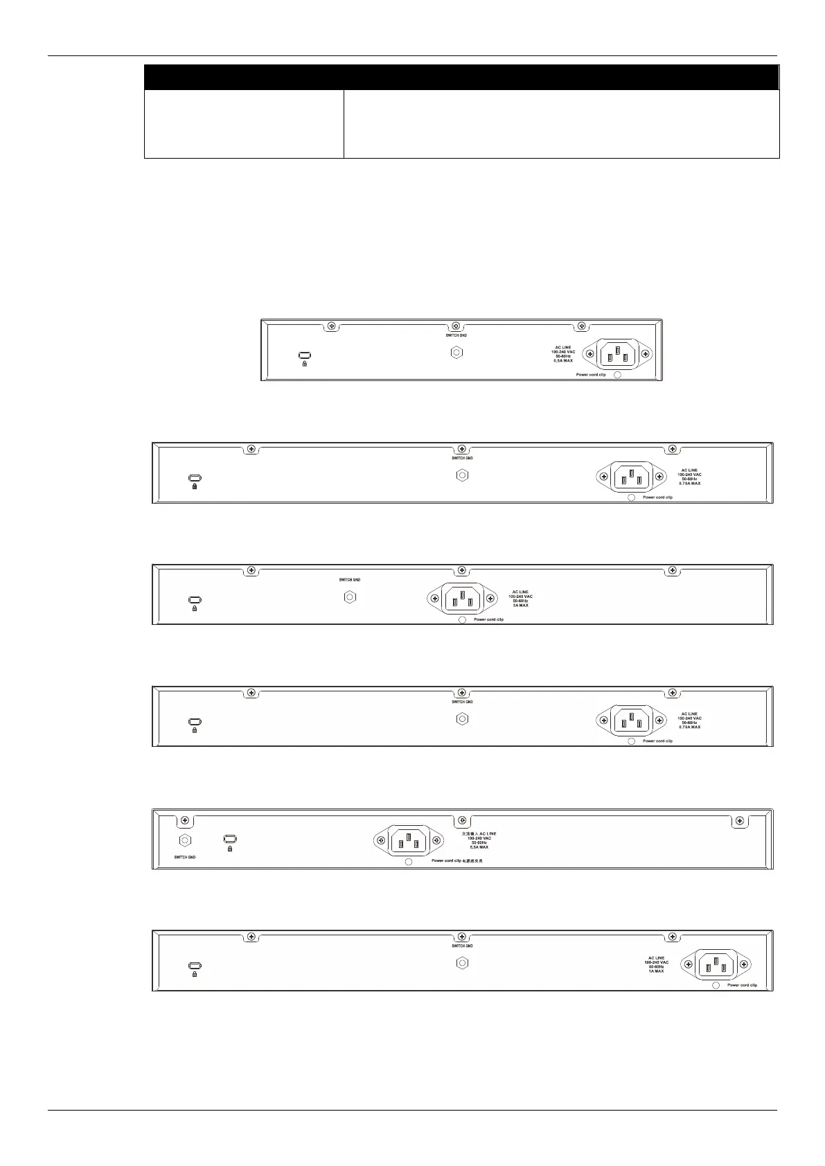
Rear Panel Components
On the rear panel of the Switch there are an AC power socket, an electrical grounding point, and a
security lock.
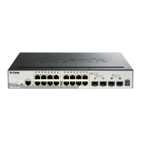
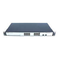
Figure 1-19 Rear panel view of a DGS-1510-20 Switch
Figure 1-20 Rear panel view of a DGS-1510-28 Switch
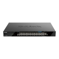
Figure 1-21 Rear panel view of a DGS-1510-28P Switch
Figure 1-22 Rear panel view of a DGS-1510-28X Switch
Figure 1-23 Rear panel view of a DGS-1510-28XMP Switch
Figure 1-24 Rear panel view of a DGS-1510-52 Switch
 Loading...