DGS-1510 Series Gigabit Ethernet SmartPro Switch Hardware Installation Guide
27
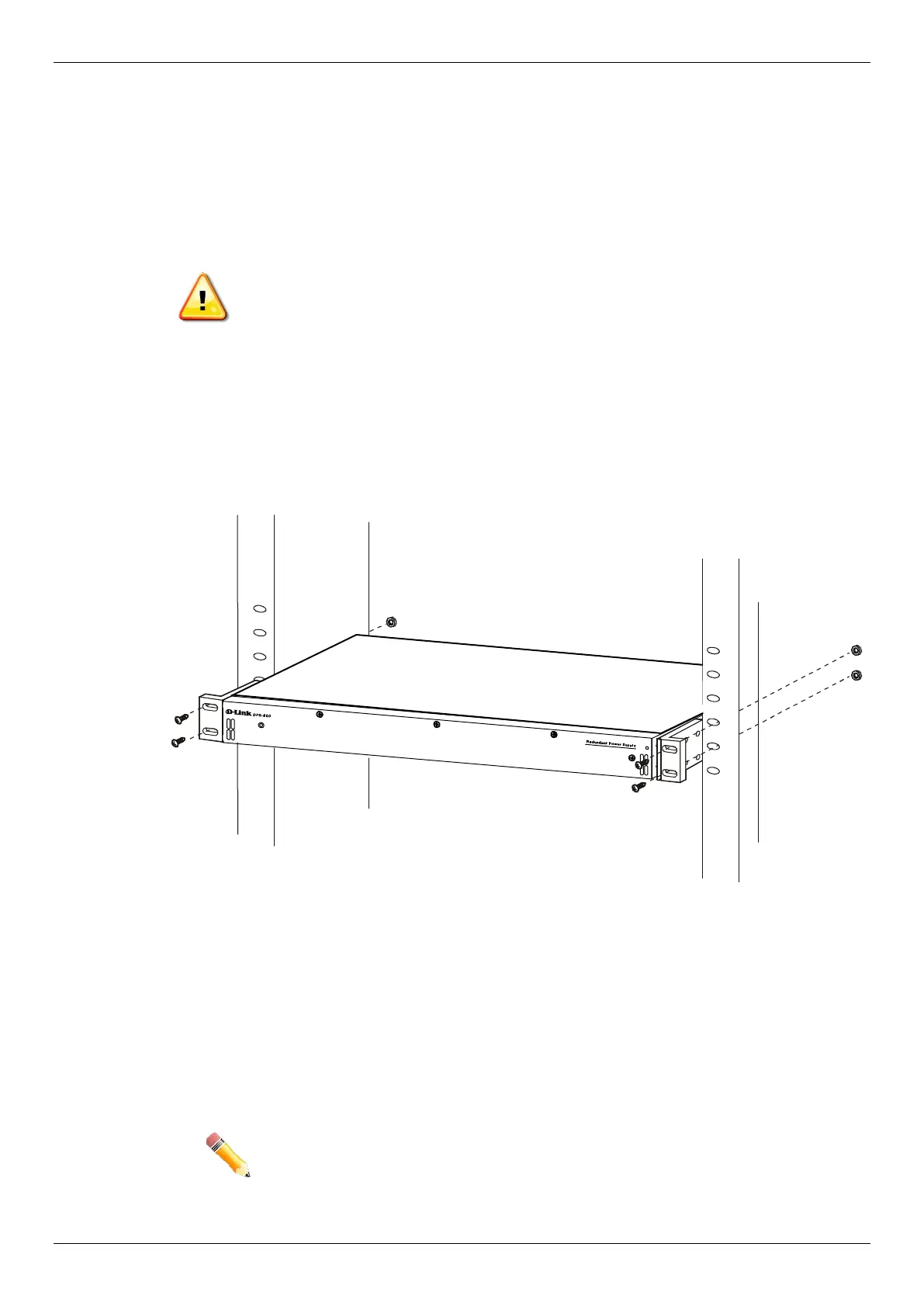
Installing the RPS into a Rack-mount Chassis
The DPS-700 is a redundant power supply unit designed to conform to the voltage requirements of
the switches being supported.
The DPS-700 can only be used with the DGS-1510-52XMP.
CAUTION: DO NOT connect the RPS to AC power before the DC power cable is
connected. This might damage the internal power supply.
DPS-700
The DPS-700 is connected to the Master Switch using a 22-pin DC power cable. A standard, three-
pronged AC power cable connects the redundant power supply to the main power source.
Figure 2-10 Front view of the DPS-700
1. Insert one end of the 22-pin DC power cable into the receptacle on the Switch and the other end into the
Redundant Power Supply unit.
2. Using a standard AC power cable, connect the redundant power supply to the main AC power source. A
green LED on the front of the DPS-700 will glow to indicate a successful connection.
3. Re-connect the Switch to the AC power source. The LED indicator will show that a redundant power supply is
now in operation.
4. No configuration in the Switch’s firmware is needed for this installation.
NOTE: See the RPS Quick Installation Guide for more information.
 Loading...