Maintenance Trigger
A maintenance trigger can be activated to show a notice on
the panel display when e.g. drive power consumption has
exceeded the dened trigger point.
Settings
Parameter Group 29: Maintenance Trig, page 53
Acceleration and Deceleration Ramps
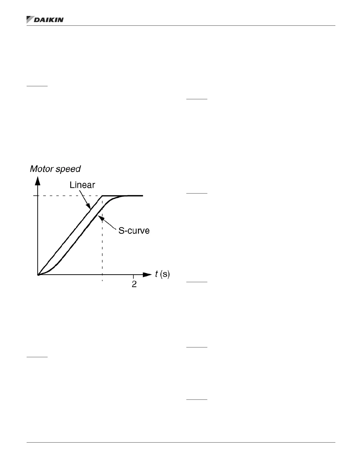
Two user-selectable acceleration and deceleration ramps are
available. It is possible to adjust the acceleration/deceleration
times and the ramp shape. Switching between the two ramps
can be controlled via a digital input or eldbus. The available
ramp shape alternatives are Linear and S-curve.
Figure 19: Acceleration And Deceleration Ramps
Linear: Suitable for drives requiring steady or slow
acceleration/deceleration.
S-curve: Ideal for conveyors carrying fragile loads, or other
applications where a
smooth transition is required when changing the speed.
Settings
Parameter Group 22: Accel/Decel, page 50
Critical Speeds
A Critical Speeds function is available for applications where
it is necessary to avoid certain motor speeds (drive output
frequencies) or speed bands (output frequency bands)
because of eg mechanical resonance problems. The user can
dene three critical frequencies or frequency bands.
Settings
Parameter Group 25: Critical Speeds, page 51
Constant Speeds
It is possible to dene seven positive constant speeds.
Constant speeds are selected with digital inputs. Constant
speed activation overrides the external speed reference.
Constant speed selections are ignored if
• PID reference is being followed, or
• Drive is in local control mode.
This function operates on a 2 ms time level.
Settings
Parameter Group 12: Constant Speeds, page 42
Constant speed 7 (1208 CONST SPEED 7) is also used for
fault functions, page 42. See parameter group Group 30:
Fault Functions, page 53.
Programmable Protection Functions
AI<Min
AI<Min function denes the drive operation if an analog input
signal falls below theset minimum limit.
Settings
Parameters 3001 AI<MIN FUNCTION, 3021 AI1 FAULT LIMIT
and 3022 AI2 FAULTLIMIT, page 53
Panel Loss
Panel Loss function denes the operation of the drive if the
control panel selected as control location for the drive stops
communicating.
Settings
Parameter 3002 PANEL COMM ERR, page 53
External Fault
External Faults (1 and 2) can be supervised by dening one
digital input as a source for an external fault indication signal.
Settings
Parameters 3003 EXTERNAL FAULT 1 and 3004 EXTERNAL
FAULT 2, page 53
program feaTures
www.DaikinApplied.com 27 OM 1190-1 • MD4 VFD

 Loading...


