InTroduCTIon
InTroduCTIon
This section describes applicability, target audience and purpose of this manual. It describes the contents of this manual
and refers to a list of related manuals for more information. The chapter also contains a owchart of steps for checking
the delivery, installing and commissioning the drive. The owchart refers to chapters/sections in this manual.
Applicability
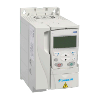
The manual is applicable to the ACS320 drive rmware version
4.00E or later. See parameter 3301 FW VERSION on page
56.
Target Audience
The reader is expected to know the fundamentals of electricity,
wiring, electrical components and electrical schematic symbols.
The manual is written for readers worldwide. Both SI
and imperial units are shown. Special US instructions for
installations in the United States are given.
Purpose of the Manual
This manual provides information needed for planning the
installation, installing, commissioning, using and servicing the
drive.
Categorization by Frame Size
The ACS320 is manufactured in frame sizes R0…R4. Some
instructions and other information which only concern certain
frame sizes are marked with the symbol of the frame size
(R0…R4). To identify the frame size of your drive, see the table
in section Ratings, types and voltages on page 102.
Contents of this Manual
The manual consists of the following chapters:
• Safety (page 5) gives safety instructions you must
follow when installing, commissioning, operating and
servicing the drive.
• Introduction to the manual describes applicability, target
audience, purpose and contents of this manual. It also
contains a quick installation and commissioning owchart.
• Operation principle and hardware description (page
7) describes the operation principle, layout, power
connections and control interfaces, type designation label
and type designation information in short.
• Start-Up (page 12) tells how to start up the drive as
well as how to start, stop, change the direction of the
motor rotation and adjust the motor speed through the I/O
interface
• Program features (page 24) describes program
features with lists of related user settings, actual signals,
and fault and alarm messages.
• Actual signals and parameters (page 30) describes
actual signals and parameters. It also lists the default
values for the different macros.
• Fault tracing (page 90) tells how to reset faults and
view fault history. It lists all alarm and fault messages
including the possible cause and corrective actions.
Maintenance and hardware diagnostics (page 99)
contains preventive maintenance instructions and LED
indicator descriptions.
• Technical data (page 102) contains technical
specications of the drive, eg. ratings, sizes and technical
requirements as well as provisions for fullling the
requirements for CE and other marks.
OM 1190-1 • MD4 VFD 6 www.DaikinApplied.com
InTroduCTIon

 Loading...


