Group 30: Fault Functions
This group denes situations that the drive should recognize as potential faults and denes how the drive should
respond if the fault is detected.
Table 37: Group 30: Fault Functions
Code Description Range Resolution Default S
3001 AI<MIN FUNCTION 0…3 1 0
Denes the drive response if the analog input (AI) signal drops below the fault limits and AI is used in reference chain.
• 3021 AI1 FAULT LIMIT and 3022 AI2 FAULT LIMIT set the fault limits
0 = NOT SEL – No response.
1 = FAULT – Displays a fault (7, AI1 LOSS or 8, AI2 LOSS) and the drive coasts to stop.
2 = CONST SP7 – Displays a warning (2006, AI1 LOSS or 2007, AI2 LOSS) and sets speed using 1208 CONST SPEED 7.
3 = LAST SPEED – Displays a warning (2006, AI1 LOSS or 2007, AI2 LOSS) and sets speed using the last operating level. This value is the average speed
over the last 10 seconds.
Warning! If you select CONST SP7 or LAST SPEED, make sure that continued operation is safe when the analog input signal is lost.
3002 PANEL COMM ERR 1…3 1 1
Denes the drive response to a control panel communication error.
1 = FAULT – Displays a fault (10, PANEL LOSS) and the drive coasts to stop.
2 = CONST SP7 – Displays a warning (2008, PANEL LOSS) and sets speed using 1208 CONST SPEED 7.
3 = LAST SPEED – Displays a warning (2008, PANEL LOSS) and sets speed using the last operating level. This value is the average speed over the last 10
seconds.
Warning! If you select CONST SP7 or LAST SPEED, make sure that continued operation is safe when the control panel communication is lost.
3003 EXTERNAL FAULT 1 -6…6 1 0
Denes the External Fault 1 signal input and the drive response to an external fault.
0 = NOT SEL – External fault signal is not used.
1 = DI1 – Denes digital input DI1 as the external fault input.
• Activating the digital input indicates a fault. The drive displays a fault (14, EXTERNAL FAULT 1) and the drive coasts to stop.
2…6 = DI2…DI6 – Denes digital input DI2…DI6 as the external fault input.
• See DI1 above.
-1 = DI1(INV) – Denes an inverted digital input DI1 as the external fault input.
• De-activating the digital input indicates a fault. The drive displays a fault (14, EXTERNAL FAULT 1) and the drive coasts to stop.
-2…-6 = DI2(INV)…DI6(INV) – Denes an inverted digital input DI2…DI6 as the external fault input. See DI1(INV) above.
3004 EXTERNAL FAULT 2 DO NOT CHANGE!! -6…6 1 0
Denes the External Fault 2 signal input and the drive response to an external fault.
• See parameter 3003 above.
3005 MOT THERM PROT DO NOT CHANGE!! 0, 2 1 1
Denes the drive response to motor overheating.
0 = NOT SEL – No response and/or motor thermal protection not set up.
1 = FAULT – When the calculated motor temperature exceeds 90 C, displays a warning (2010, MOT OVERTEMP). When the calculated motor temperature
exceeds 110 C displays a fault (9, MOT OVERTEMP) and the drive coasts to stop.
2 = WARNING – When the calculated motor temperature exceeds 90 C, displays a warning (2010, MOT OVERTEMP).
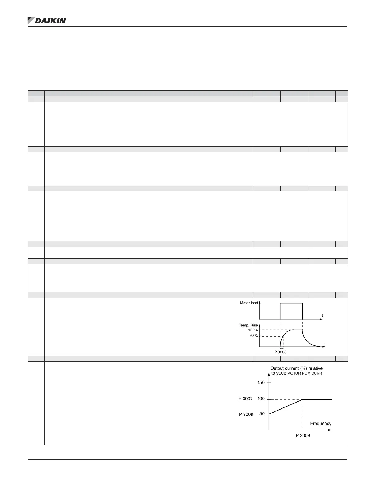
3006 MOT THERM TIME DO NOT CHANGE!! 256…9999 s 1 1050 s
Sets the motor thermal time constant for the motor temperature model.
• This is the time required for the motor to reach 63% of the nal temperature with steady load.
• For thermal protection according to UL requirements for NEMA class motors, use the rule of
thumb: MOTOR THERM TIME equals 35 times t6, where t6 (in seconds) is specied by the
motor manufacturer as the time that the motor can safely operate at six times its rated current.
• The thermal time for a Class 10 trip curve is 350 s, for a Class 20 trip curve 700 s, and for a
Class 30 trip curve 1050 s.
3007 MOT LOAD CURVE DO NOT CHANGE!! 50…150% 1 100%
Sets the maximum allowable operating load of the motor.
• With the default value 100%, motor overload protection is functioning when the constant
current exceeds 127% of the parameter 9906 MOTOR NOM CURR value.
• The default overloadability is at the same level as what motor manufacturer’s typically
allow in the 86°F (30°C) ambient temperature and 3300 ft (1000m) altitude. When the
ambient temperature exceeds 86°F (30°C) or the installation altitude is over 3300 ft
(1000m), decrease the parameter 3007 value according to the motor manufacturer’s
recommendation.
Example: If the constant protection level needs to be 115% of the motor nominal current,
set parameter 3007 value to 91% (=115/127*100%).
aCTual sIgnals and parameTers
www.DaikinApplied.com 53 OM 1190-1 • MD4 VFD